Tile Tip
By Scott Carothers
Director of Certification and
Training for CTEF
Don’t Skip These Steps: How to Successfully Install Cementitious Backer Units Under Tile
Photo: peshkov/iStock/Getty Images Plus via Getty Images.
The American National Standards Institute (ANSI) specifications are the basis for both the materials used on a project, as seen in ANSI A118, and the installation methods used, as seen in ANSI A108. The manufacturers produce products for the tile industry that either meet or exceed these standards along with installation recommendations.
The rule of three, in this case, applies to the installation of cementitious backer units (CBU), commonly known as cement backer board. There are several installation procedures required for a successful cement backer board floor installation over a wood subfloor, but the critical three include the placement of mortar between the substrate and the underside of the board, proper fasteners, and placement, and applying mesh tape along the edges.

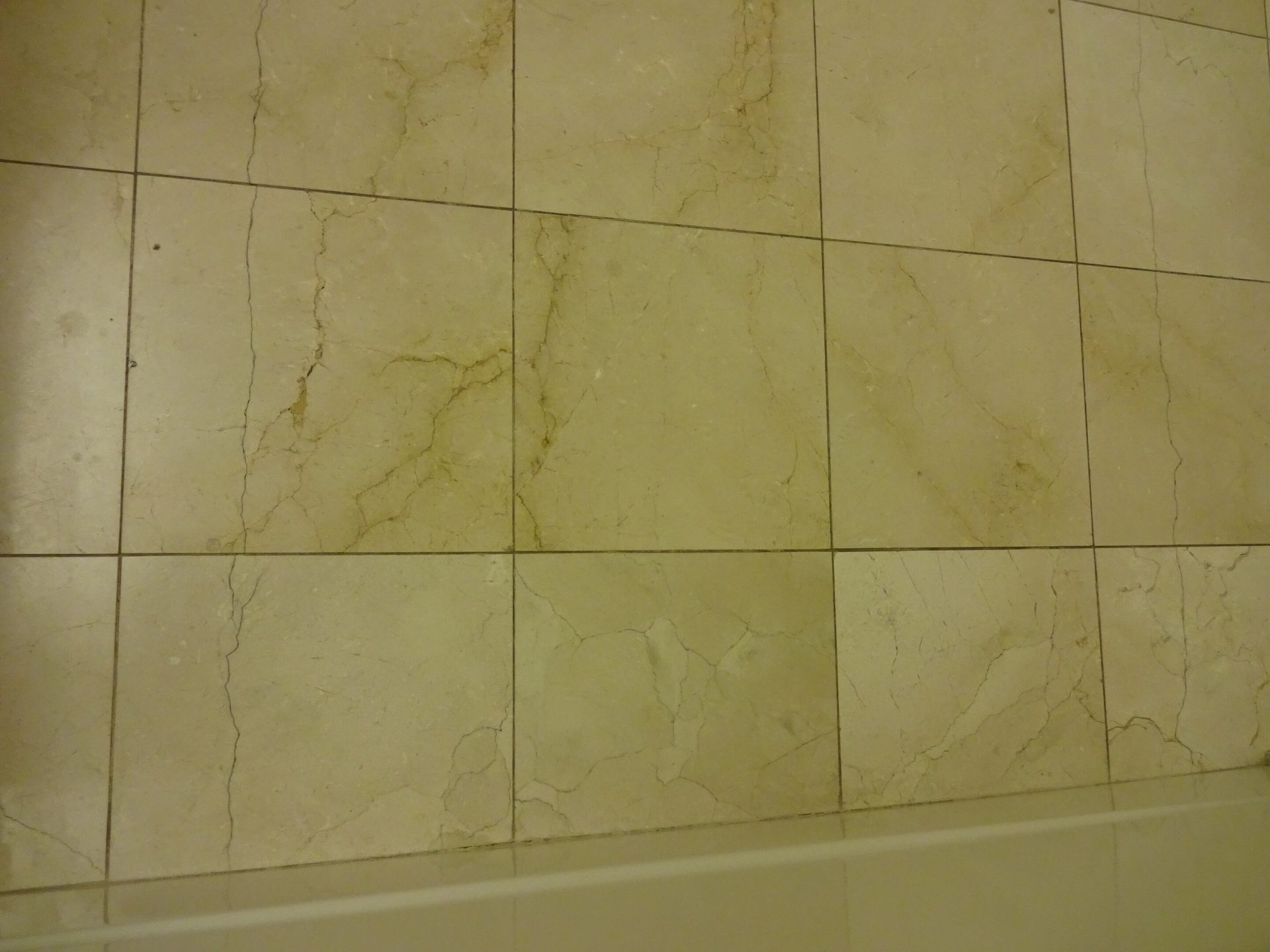
The cracks seen in this failure image were caused by the installer not applying the manufacturer's required coated glass fiber joint tape to the joints between the backer board. Photo: Scott Carothers.
ANSI A108.11 Interior Installation of Cementitious Backer Units (CBU) provides guidance on the installation of CBUs on a floor installation.
Section 5.2.1 states, “Install CBU over plywood subfloor as described above in 4.3 (subfloor 19/32in. [16 mm] or thicker plywood) after application of a bedding coat of dry-set cement mortar or adhesive to the subfloor for a minimum thickness of 3/32 in. (2 mm) coverage to provide a uniform support between the cementitious backer unit and the subfloor following the mortar or adhesive manufacturer’s recommendations. CBU shall be placed and secured before setting material films over.”
Section 3.1.1 declares, “For wood framing, use corrosion resistant roofing nails (11 ga. x 3/8 in. HD) such as hot-dipped galvanized, or equal, of sufficient length to penetrate the wood framing a minimum of 3/4 in. (19 mm) or corrosion resistant wood screws (minimum No.8-18 x 3/8 in. HD ribbed wafer). Screw length must provide a minimum of 3/4 in. (19 mm) thread engagement.”
Section 5.2.2 states, “Stagger CBU joints so as not to coincide with joints in subfloor. CBU must be fastened with galvanized nails, screws, or other manufacturer-approved corrosion-resistant fasteners 8 in. (20 cm) on center in the field and around all edges.”
Section 3.2.1 states, “Tape: Coated glass fiber mesh tape as required for joint treatment by CBU manufacturer.”
Section 5.5.1 asserts, “Fill all joints of CBUs with tile setting material and tape according to manufacturer’s requirements.”
These last two ANSI standards, which require alkali-resistant (not drywall) tape to be installed on the CBU joints, are critical to a successful CBU installation. Not taping the joints, as seen in the attached image, is the reason that the three feet on center parallel cracks in the stone tile caused this failure. The purpose of the tape is to create a monolithic surface for the tile installation. Without the tape, each piece of CBU can move independently (rather than one piece) which results in the crack.
The standards and the manufacturers provide very detailed requirements and guidance for the successful installation of their products. The simple need of the installation community is to follow these directives and success is guaranteed.


