INDUSTRIAL GASES/COMBUSTION
SafakOguz/iStock / Getty Images Plus via Getty Images
Combustion Equipment for Energy Recovery: There’s More to it Than Just Saving Fuel
Dennis Quinn – Fives North American Combustion; Cleveland, Ohio
Today’s combustion systems are efficient, have low environmental footprint and deliver quality heating of the product.
It is increasingly necessary for sustainable businesses to consider the impact of their operations on their upstream suppliers and downstream customers. Heightened awareness of corporate social responsibilities, growing concern over environmental footprints and continued operation of a financially sustainable business all must be respected to optimize the viability of the operation.
The purpose of this article is to provide a framework for thermal-efficiency considerations when evaluating a new or upgraded combustion system. A detailed approach to assess each of the variables would be too much to cover in a single article. Moreover, this article is limited to industrial burner systems and does not consider electric as an energy source. This is not to suggest that electric heating should be eliminated from a similar evaluation. The method of electric generation can have significant emissions and carbon-footprint impacts when considered as an upstream resource.
Thanks to progressive development by combustion equipment manufacturers and integrators, systems are available today that are aligned with the objectives of a sustainable business. Current systems are efficient, have low environmental footprint and deliver quality heating of the product – the main objectives of a combustion system.

Balancing these business objectives has not always been the goal. While maximizing fuel efficiency may make logical sense, North America has enjoyed low energy costs due to abundant supply, limiting the application of increased efficiency applications. Early attempts to increase energy efficiency resulted in high NOx emissions. Modern developments have reduced these emissions, in many instances, below what is produced by traditional ambient combustion air systems. At the hands of trained professionals, heat recovery has now evolved as an important tool to effectively address current industrial combustion system objectives.
How is efficiency defined, and how do we improve it?
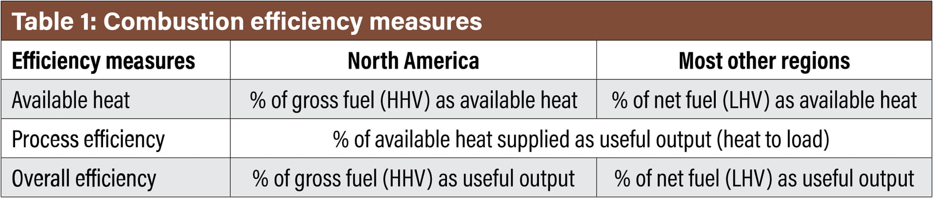
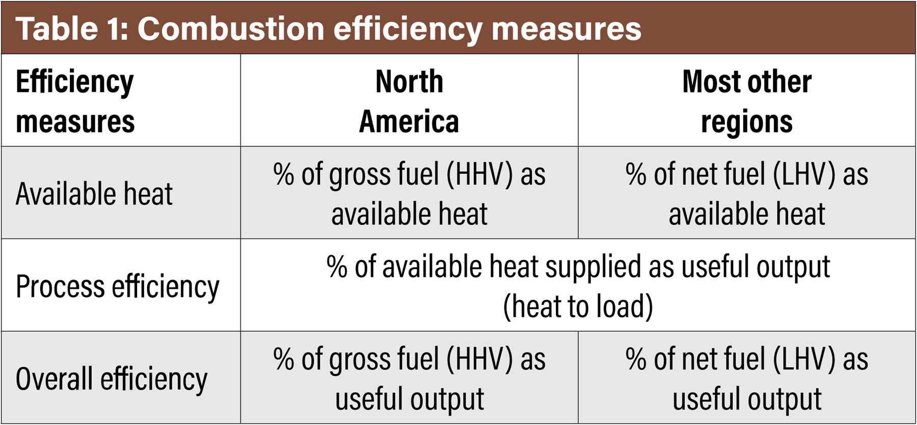
Combustion efficiency reporting depends on industry segment norms and geographical regions. Therefore, it is important to start any discussion on efficiency with a quick review so that there is a comprehensive understanding between these comparisons. Table 1 illustrates three measures of efficiency defined by several norms and by continental locations.
For the North American continent, the higher heating value (HHV) of the fuel is typically referenced. In most other countries, the lower heating value (LHV) will be referenced. The difference is HHV includes the enthalpy of the water vapor in the exhaust stream, whereas LHV does not. For most gaseous fuels, the HHV is 11-18% higher than the LHV. Therefore, it becomes very important to understand the basis so that an accurate comparison can be made across various options. The same is true for emissions references.
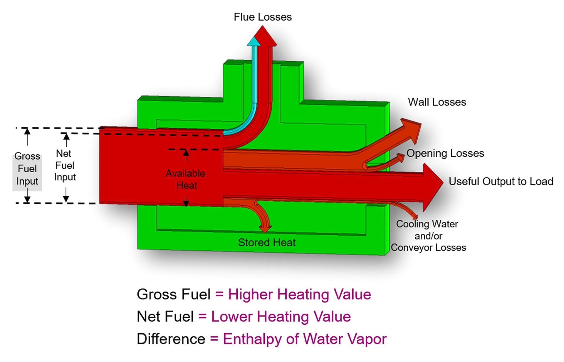
Fig. 1. The Sankey Diagram
The common metric for measuring combustion efficiency, “available heat,” is defined as the percentage of the energy input that is available to the process. An excellent visual tool to understand available heat is shown in Fig. 1.
The Sankey diagram illustrates that only a portion of the fuel energy delivered is “available” to the process. This available portion is equal to the incoming fuel minus the energy carried out of the furnace stack. Some of this is contained in water vapor with the balance as sensible heat of the gases.
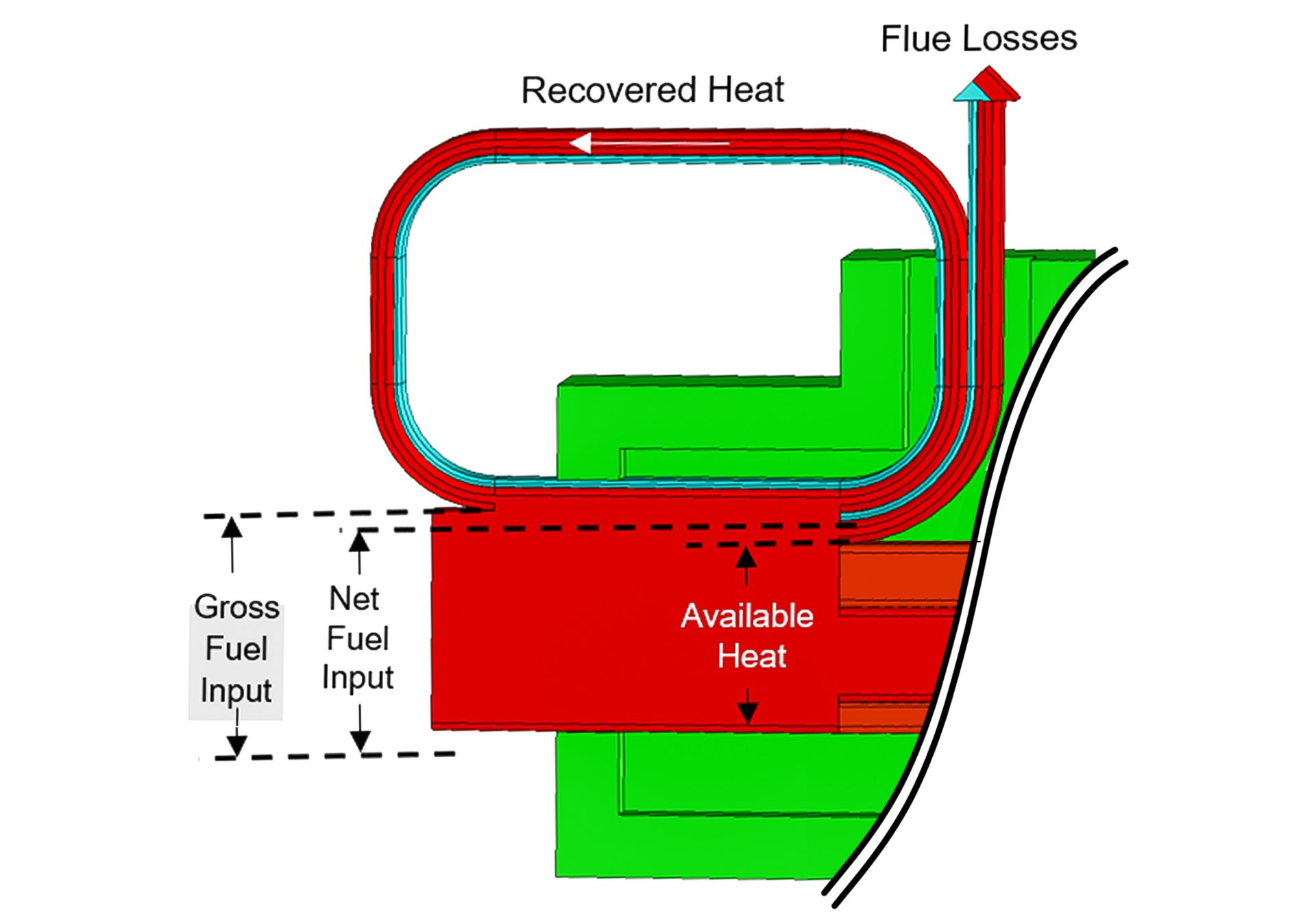
To improve efficiency, a portion of the energy exiting the flue (flue losses) is returned to the process. Fig. 2 illustrates how this return of energy is represented in the Sankey diagram.
Referencing the HHV, the available heat typically ranges from around 30% for high-temperature ambient combustion air systems to as high as 80% for high heat-recovery options. It is important to emphasize again that the available heat for most fuels is approximately 10% higher when reported against the lower heating value. Conversely, the available heat is approximately 10% lower when reported against the higher heating value.
Once the available heat from a heat-recovery option is understood, the relative fuel consumption for each may be calculated. The consumption is calculated using the available heat and the required thermal input (Equation 1).
Fig. 2. The flue portion of the Sankey diagram with energy recovery


With a given available heat, the relative fuel consumption can be determined by using Equation 2.
For example, assuming the current fuel use is with an ambient air burner firing a process at 2000°F (1093°C), the available heat would be 42%. For the same process, temperature preheating the combustion air to a modest 800°F (427°C) will increase the available heat to around 56% and result in a fuel savings of 25%. Knowing the current fuel requirements and costs, one can quickly estimate the fuel cost savings over a given period.
Using existing fuel consumption data almost always improves the accuracy of the fuel savings estimate. Actual data integrates variables that are otherwise difficult to predict, such as variable utilization and variable inputs. Otherwise, performing an accurate estimation requires detailed thermal process modeling completed with a full product mix analysis.
Systems for Recovering Energy and Improving Efficiency
Transferring a portion of the thermal energy contained in the flue gases to the incoming combustion air stream is the system most often applied for heat recovery. The incoming fuel may likewise be preheated, especially for low-calorific-value fuels.
A heat exchanger placed in the flue gas stream is used to transfer the energy to the combustion air. In industry today, two methods are prevalent: heat recuperation and heat regeneration. Heat recuperation is a steady-state process with continuous heat transfer. Heat regeneration alternatively stores and recovers heat into a heat storage media.
Heat Recuperation
Recuperation is an industry term to describe a heat exchanger placed into an exhaust stream to “recuperate” heat otherwise lost. In application, there are many variations of designs and applications, but all can be generally characterized as distributed or centralized.
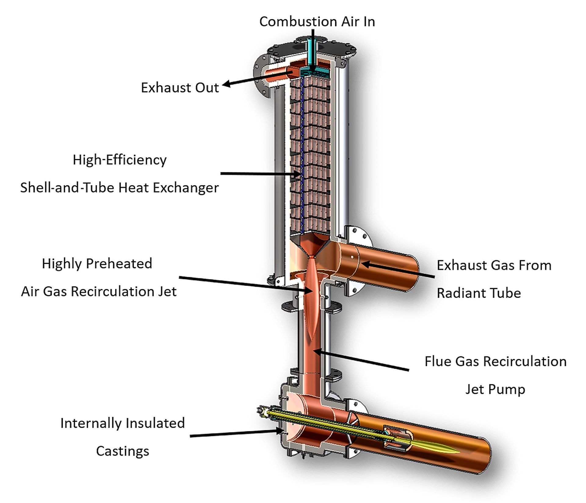
In distributed recuperation systems, the recuperators are located near or within the burner. Being closely coupled, or integral to the burner, these systems typically operate at higher efficiencies than centralized recuperation. These systems provide maximum efficiency by reducing the thermal losses between the recuperator andburner. Fig. 3 illustrates a typical modern distributed system for radiant-tube combustion systems.
Fig. 3. Distributed recuperation applied to a radiant-tube system
Central recuperation is generally utilized where large numbers of burners are applied, such as tunnel, catenary, reheat, melting or enameling furnaces. The exhaust stream from the furnace is collected, sometimes further oxidized if there is a reducing atmosphere, and directed to a centralized recuperator. Preheated combustion air is returned to a series of preheated air-style burners through a hot air distribution network.
While centralized recuperative systems have slightly lower efficiency, they are often the correct choice for systems that contain a large number of burners, such as in continuous processing lines. Fig. 4 illustrates a typical centralized recuperative system.
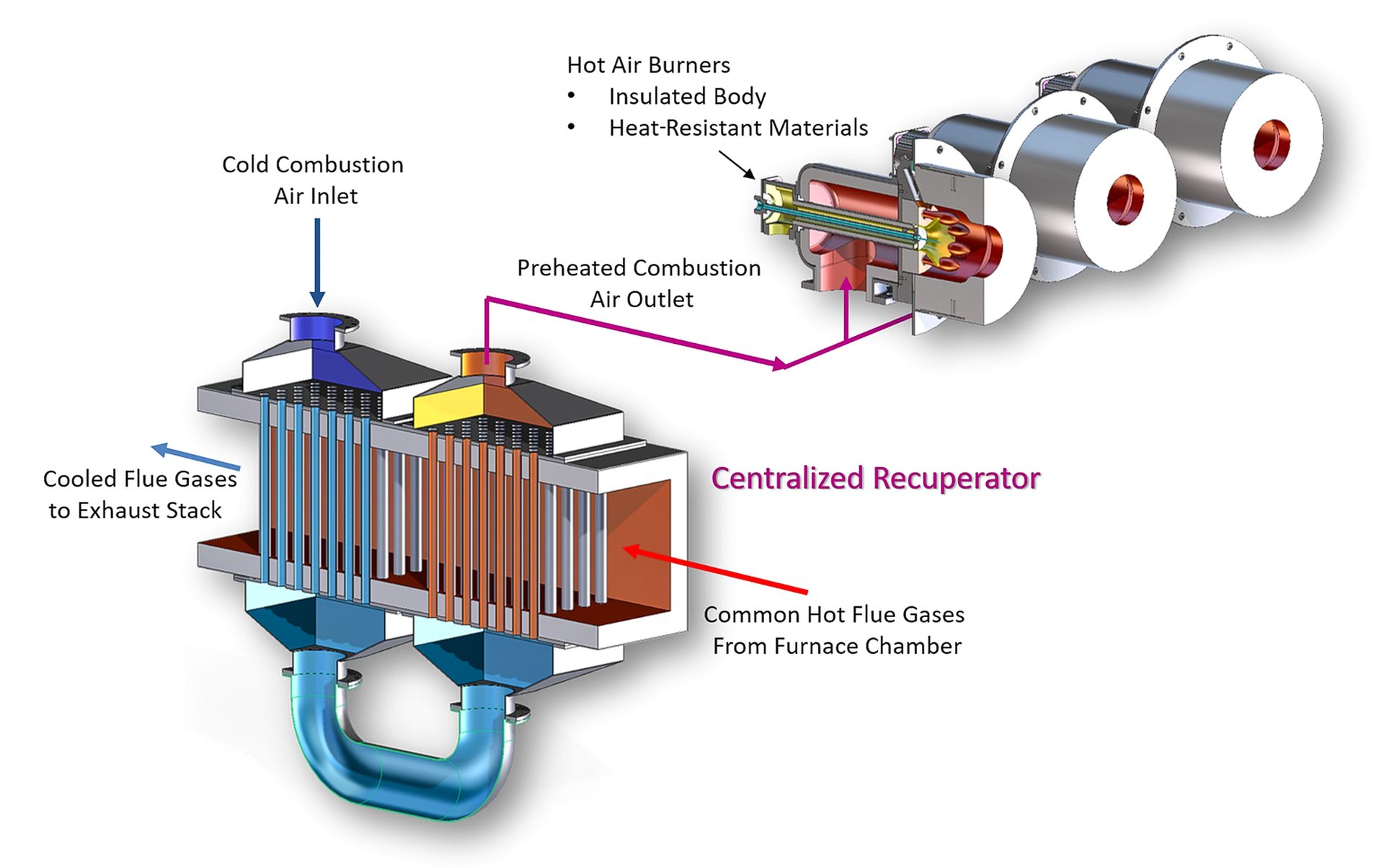
Fig. 4. Centralized recuperation system
Heat Regeneration
Regenerative systems cycle between flue gases and combustion airflow, extracting heat from the flue gases and returning the energy to the incoming combustion air at a later time.
Early versions of regenerators were installed centrally, which can be seen in early glass-melting or steel open-hearth furnaces. Now, most modern regenerators are distributed and integrated within or closely coupled to the burner. This new methodology is very similar to their recuperative counterparts. The closely coupled arrangement eliminates the need for extremely hot ducting and valves that would be required with a centralized system. Close coupling also allows the cycling components to be placed on the cooled side of the regenerator, where long operating life is realized.
Exhaust is passed over the regenerator, where the energy in the flue gases is stored, during part of the regenerative cycle. Combustion air is then passed over the same regenerator to recover energy and deliver it back to the process.
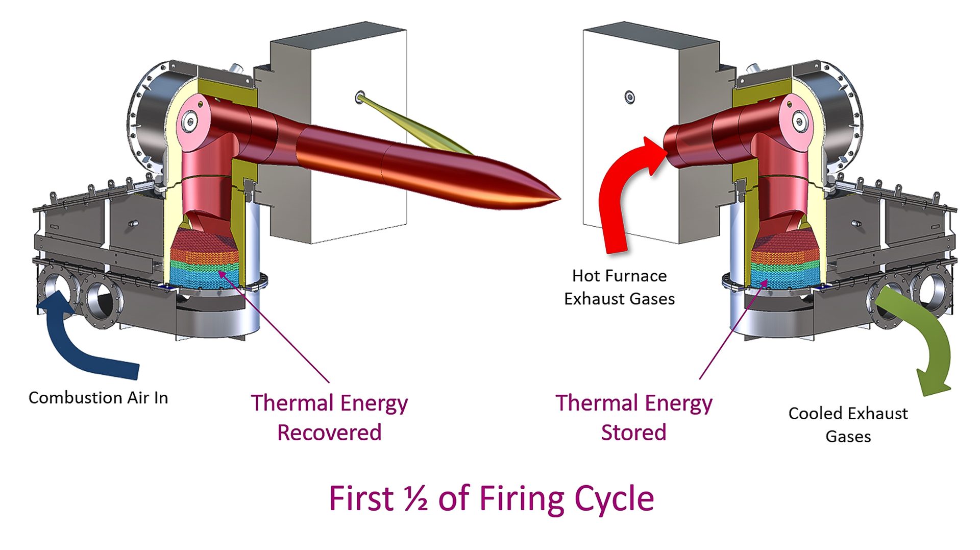
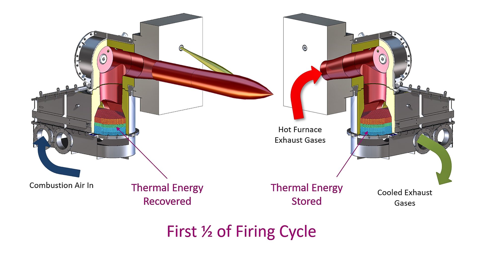
Fig. 5. Direct-fired regenerative burners
Since part of the cycle involves exhausting through the burner, the heat delivered to the process is periodic. To ensure that there is continuous heat flow, regenerative burners are grouped in sets of two or three. Fig. 5 illustrates a set of regenerative burners, one in firing (heat recovery) mode and one in exhausting (heat storage) mode.
Less limited by the material duties of the wall separation required in recuperators, regenerators lend themselves to being more compact. Packed beds of ceramic media or honeycomb ceramic allow the highest levels of efficiency to be achieved in compact physical volumes, typically 10-15% higher efficiency than recuperators. Fig. 6 illustrates compact regenerative burners applied to a radiant-tube burner system.
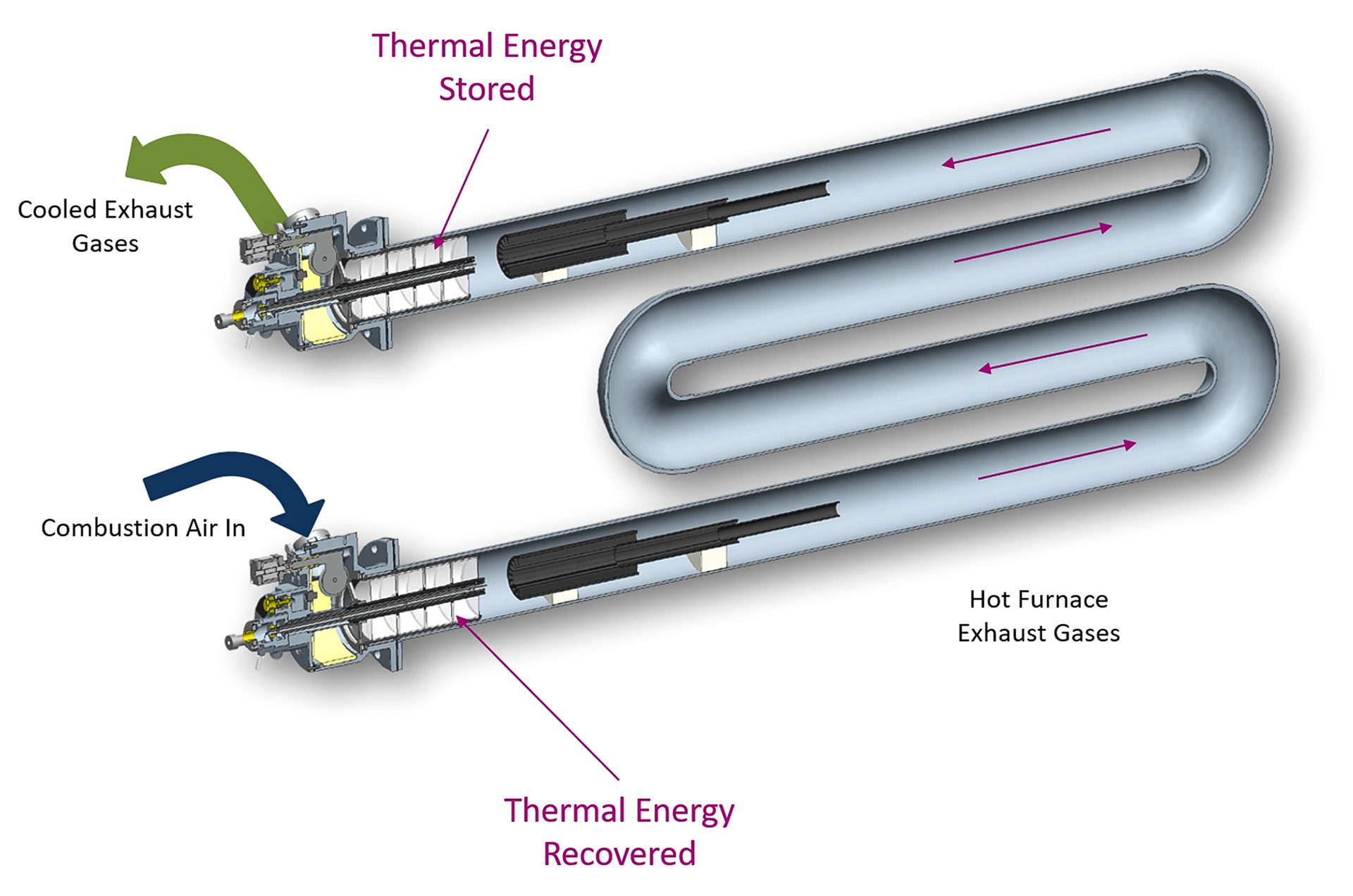
Fig. 6. Honeycomb-style radiant-tube regenerative burner
Heat Recovery’s Role in Emissions
In the past, high flame temperatures have limited the application of heat-recovery equipment due to increases in NOx emissions. Particularly in areas that regulate to a threshold limit – parts per million, for instance – without credit to heat recovery, the higher emissions associated with heat recovery were not accepted. This point remains in some areas today, unfortunately at the expense of the environment.
To solve the issue, currently available combustion equipment reduces the emissions below what is produced by many ambient systems. These modern heat-recovery systems can deliver significant mass-based emissions reduction over conventional systems thanks to the reduction in fuel consumption, which has been optimized by the heat-recovery equipment.
Heat Recovery and Greenhouse Gas Emissions
As the narrative continues to evolve around the reduction in greenhouse gases, it is important to understand the role of heat recovery applied to the combustion system.
For combustion systems, reducing greenhouse gas emissions, specifically the reduction of CO2 emissions, is a current focus area. Fuel switching is normally thought of when addressing the carbon emissions at the source. Switching from high carbon fuels, such as coal and fuel oil, to natural gas reduces the carbon in the process and the subsequent CO2 emissions. Extended low natural gas pricing in the U.S. has resulted in the conversion of many traditional coal- and oil-fired processes, with the associated CO2 reductions already realized.
Green hydrogen, which is produced from water by renewable resources, is seen as an effective solution for the future. Either replacing or mixing with conventional fuels, hydrogen fuel reduces the carbon content of the fuel mixture, while pure hydrogen removes the carbon completely. The infrastructure to produce adequate sources of green hydrogen fuel is currently evolving. It will require significant private and public resources to develop. Until then, classical hydrogen production methods utilizing hydrocarbon fuels will have minimal impact on overall carbon emissions.
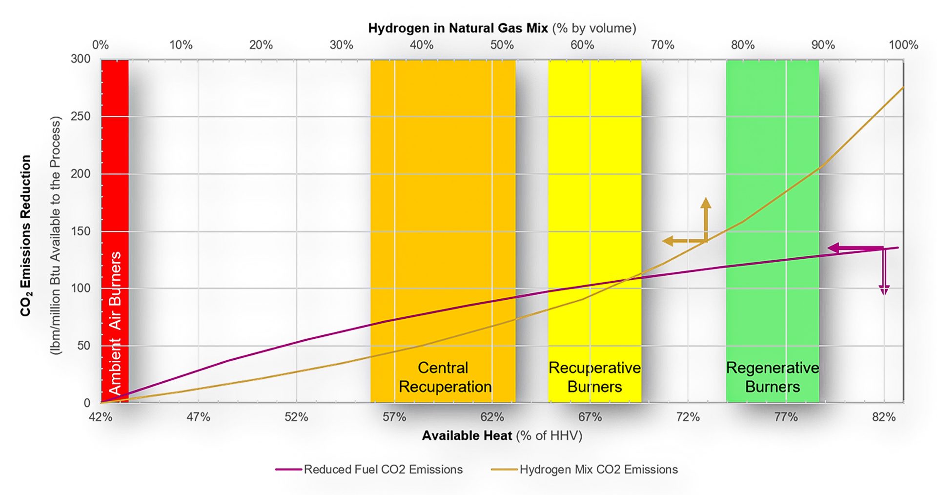
Fig. 7. CO2 emissions reduction vs. available heat and percent hydrogen mix in the fuel for a 2000°F (1093°C) process
In areas where the application of heat recovery has not fully developed, significant reductions in CO2 emissions are obtainable. Fig. 7 shows the potential.
The primary vertical axis represents the CO2 reduction in pounds of CO2 reduction per million BTU delivered to the process. On the primary horizontal axis, the available heat subject to the heat-recovery system can be found. Intersecting the magenta line, the pounds of CO2 reduction per million BTU delivered can be read from the primary vertical axis.
Similarly, the secondary horizontal axis displays the percentage of hydrogen in a natural gas mixture. Using a target blend, the percentage is followed down to intersect with the gold line. Referencing the primary vertical axis, the emissions reduction can be determined.
At the intersection of the two curves, Fig. 7 indicates that upgrading an ambient air system to a decentralized heat-recovery system can result in the equivalent of approximately 63% hydrogen in a hydrogen/natural gas blend, which is roughly a 40% reduction in CO2 emissions.
With so many considerations, how can I compare the options?
Today’s decision-making on heat recovery for combustion systems expands way beyond the classic “how much fuel will I save” question. Taking a lifecycle holistic approach, increasing interests in carbon reduction and overall emissions reduction may indeed take precedence over fuel savings in the future, especially as carbon emissions taxation increases to curb greenhouse gas emissions.
Understanding the interrelationships between thermal efficiency, fuel composition tradeoffs, NOx emissions and carbon emissions becomes a complicated matrix for the casual user to navigate. Fear not. There are multiple resources available to help inform your decisions.
Most trade organizations offer periodic training and seminars on the topic. Increasingly, technical articles are being written to raise awareness of the influence of evolving technologies. Finally, combustion equipment suppliers know the options and stand ready to provide detailed analysis of the tradeoffs for integration into your financial analysis options, enabling you to make the best decision for your sustainable business.
For more information: Dennis Quinn is Senior Product Manager, Flat Products, for Fives North American Combustion (www.fivesgroup.com) in Cleveland, Ohio. He can be reached at 216-233-6855 or dennis.quinn@fivesgroup.com.
All images provided by the author, except where noted.


INDUSTRIALHEATING.COM | BACK TO CONTENTS | JUNE 2022