Heat Treating
gorodenkoff/iStock / Getty Images Plus via Getty Images
Improved Cooling Rates in Fluidized-Bed Systems
Andreas Guderjahn – Schwing Technologies GmbH; Neukirchen-Vluyn, GERMANY
During the past few decades, fluidized-bed technology has not lost any of its importance for heat-treatment applications in terms of quality and has even become indispensable in some application niches due to its special properties.
The functioning principle (Fig. 1) of fluidized-bed heat-treatment systems from Schwing Technologies is based on patented Schwing fluidized-bed technology, where fine-grain aluminum oxide is fluidized with air or inert gas in a process chamber. The fluidized bed generated conducts heat extremely well and possesses enormous heat capacity because of its mass.
The heat-treatment systems are heated indirectly via electric heaters or gas burners and can be used over a large temperature range up to 1922°F (1050°C). Metal tools or components can be easily immersed in the fluidized bed, and in the shortest amount of time they can be preheated, annealed, nitrided, nitrocarburized, tempered, quenched or quenched and tempered with the desired atmosphere and temperature.
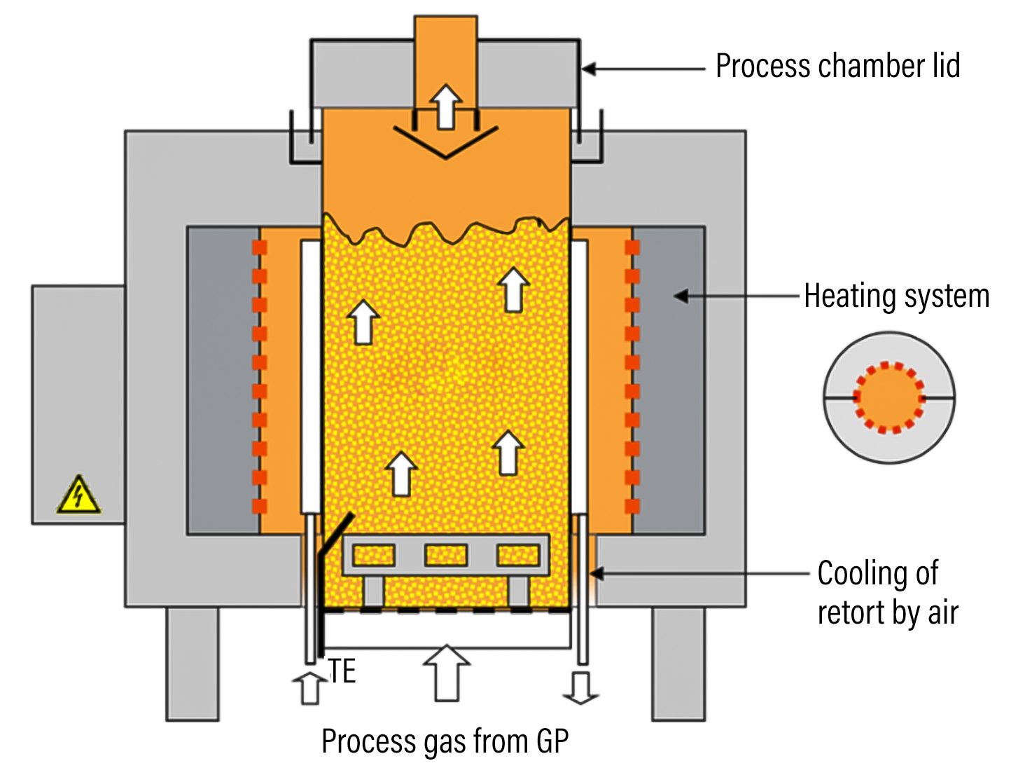
Fig. 1. Functioning principle of the fluidized-bed heat-treatment system
Advantages of Fluidized-Bed Technology
Interruptions, changeovers or changes of the treatment process and the atmosphere from thermochemical to inert are possible at any time and within only 2-3 minutes. The temperature accuracy during soaking, dwelling and heat-up and quenching ensures the non-warping treatment of the batches introduced. In addition, the excellent temperature uniformity is keeping stress in the treated parts at a very minimum, which addresses the major disadvantages of liquid quench media and high-pressure gas-quench systems. Quick and uniform heating makes standby heating obsolete. Facilities using this technology operate completely without waste.
Optimization of Cooling in the Fluidized Bed
As with many other technologies, there is sometimes a need for optimization in special application areas. One requirement that came from the market was to increase cooling rates. Among other things, alternatives to austempering in salt bath were sought, as well as alternatives to liquid quenching media such as oil or polymer for advanced-manufactured metal parts. The main aspects were environmental compatibility and the reduction or avoidance of cleaning post-treatments.

R&D Project
The optimization of the cooling effect in fluidized bed was carried out as part of a research-and-development project of Schwing Technologies, PEER Energy and the Center for Heat Treating Excellence at Worcester Polytechnic Institute (WPI) in Worcester, Mass. The focus was on austempering.
Due to the required comparability, standardized methods and samples were used. Several preliminary tests for probing the fluidization gases and bath media and all heat-treatment trials were performed at Schwing Technologies’ technical center. Metallographic examinations and material tests were carried out by WPI. This article concentrates on the third test series at Schwing Technologies for AISI 5160, where the optimization goal was achieved.
First, the current status of the cooling effect of common fluidized-bath systems had to be determined in comparison with other technologies and media. Standard parameters for the equipment, usual fluidization gases (air and nitrogen) and a common aluminum oxide for heat-treatment applications were chosen as starting point.
Austempering is a heat-treatment process based on the isothermal transformation of austenite to bainite, which forms in the temperature range between pearlite and martensite. To form the bainite, the cooling rate needs to be fast enough to avoid the formation of pearlite at higher temperature (Fig. 2).
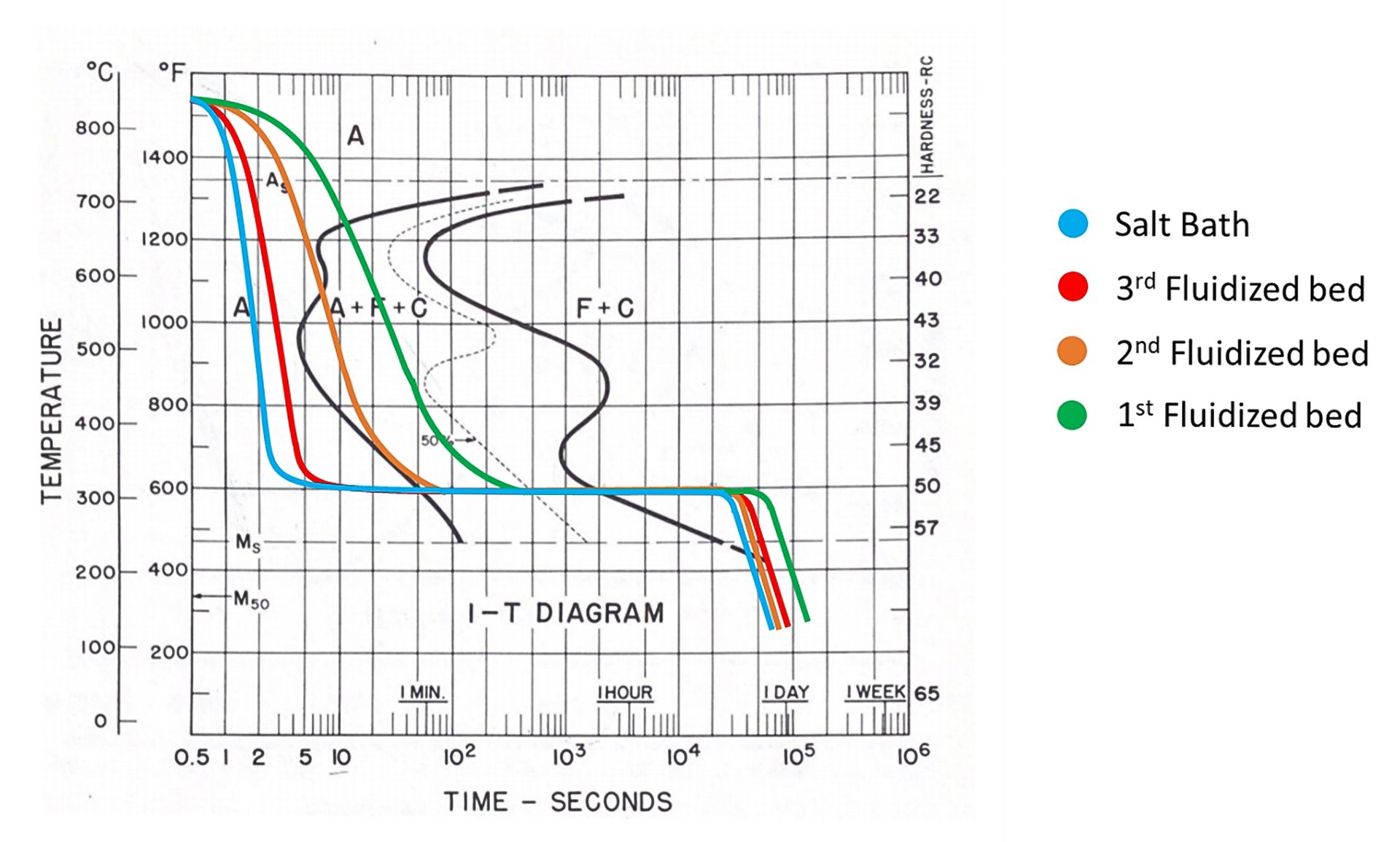
Fig. 2. Cooling rates under different conditions in a fluidized bed compared to salt bath
Then two austempering trials were conducted on AISI 5160 using fluidized bed with different fluidization gases and bath media. The first trial was performed with Al2O3 and the second with a so-called B4Q as bath medium. Both trials didn’t make the full bainite due to the slow cooling rates. With a new bath medium (called G4Q) and a special fluidization gas, the cooling rates were significantly better than the cooling rates with Al2O3 and standard gases, especially in the temperature range of 932-1472°F (500-800°C), which can be seen in Fig. 2. Therefore, it was decided to conduct the third austempering trial using the new fluidized-bed bath medium G4Q.
Fig. 3. Typical sample used for the austempering trials compared to a quarter
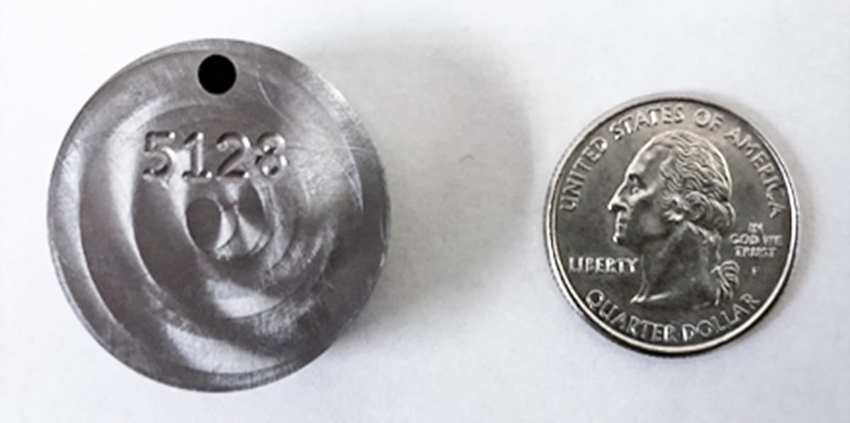
The samples were austenitized in a fluidized-bed furnace at 1562°F (850°C) for 30 minutes, then austempered in another fluidized-bed furnace at 600°F (315°C) for 1, 2, 5, 30 and 90 minutes, respectively. They were then taken out from the furnace and cooled in air to room temperature. These samples, prepared by WPI, are disks 1.125 inches in diameter and 0.5 inch thick (Fig. 3). The austempered samples were shipped back to WPI for characterization, including Rockwell hardness measurement, Vickers microhardness line scan, XRD analysis, and optical and SEM microstructure analysis.
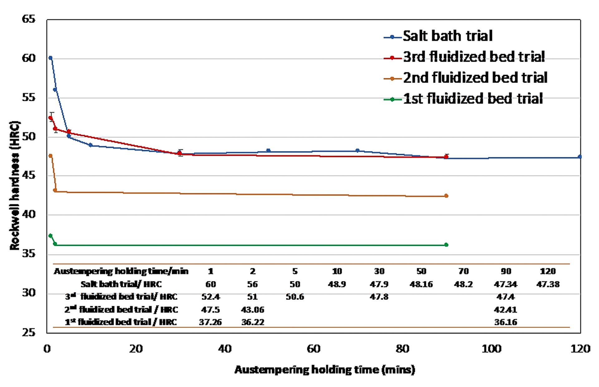
Figure 4 shows the Rockwell hardness of the austempered samples from the third fluidized-bed trial, which are compared with the Rockwell hardness of samples austempered in salt bath at the same temperature. It can be seen that the hardness data are very close for 30 minutes and 90 minutes austempering holding time samples. The hardness of austempered samples from the first and second trials are also shown in Fig. 4. It can be seen that the hardness of 90 minutes austempering holding time samples from both the first and second trials are lower than the hardness of the sample from the third trial with same austempering holding time.
Fig. 4. Rockwell hardness comparison of salt-bath and fluidized-bed austempered samples
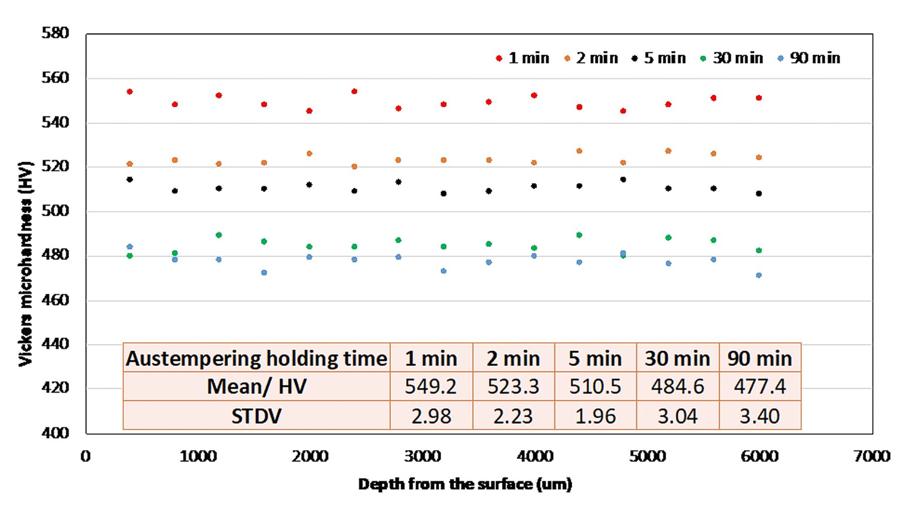
The samples were cut, mounted and polished for the Vickers microhardness measurements by a Wilson VH3300 (0.5kgf). The Vickers microhardness line scan was conducted on the cross section of these samples from surface to the core. The results are shown in Fig. 5, with calculated average microhardness and standard deviation. It can be seen that the microhardness is uniform in each sample. The Vickers microhardness decreases with the austempering time increasing, which is in good agreement with the Rockwell hardness measurement results.
Fig. 5. Vickers microhardness line scan of the samples from the third trial with G4Q bath medium
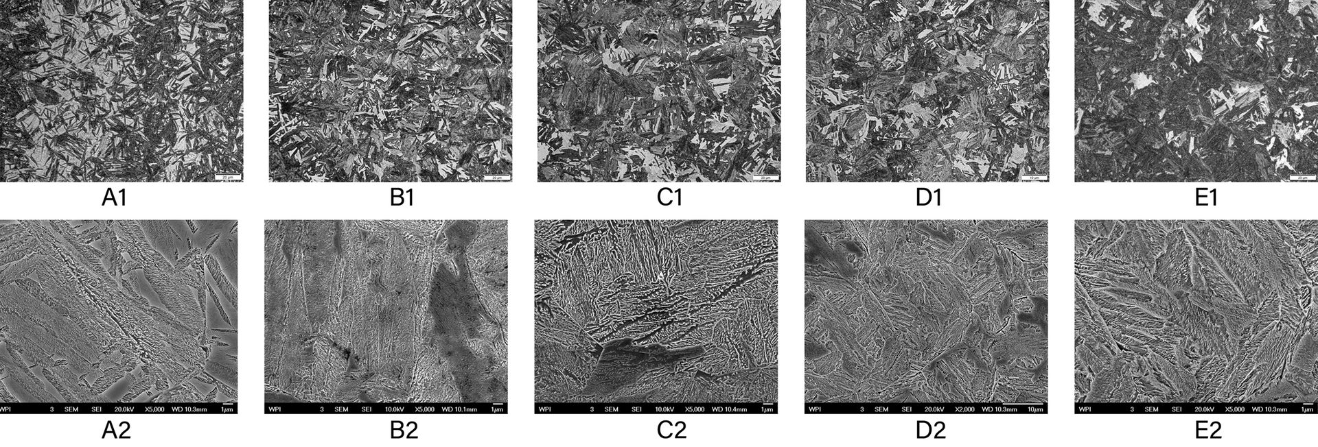
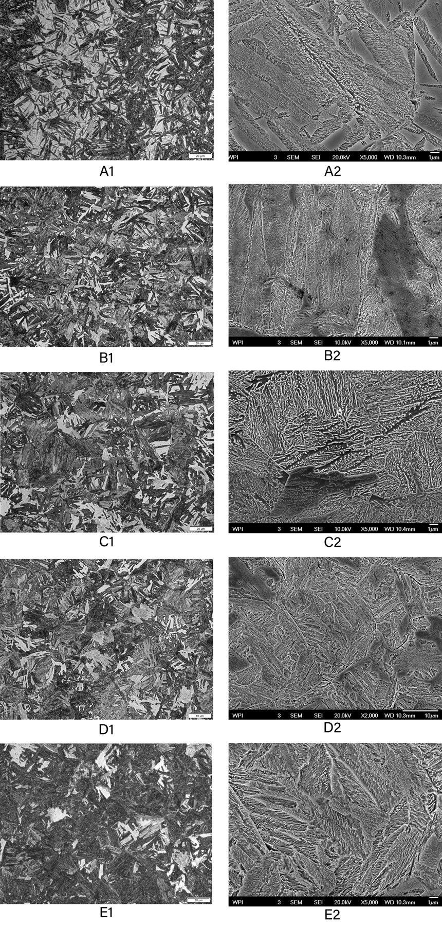
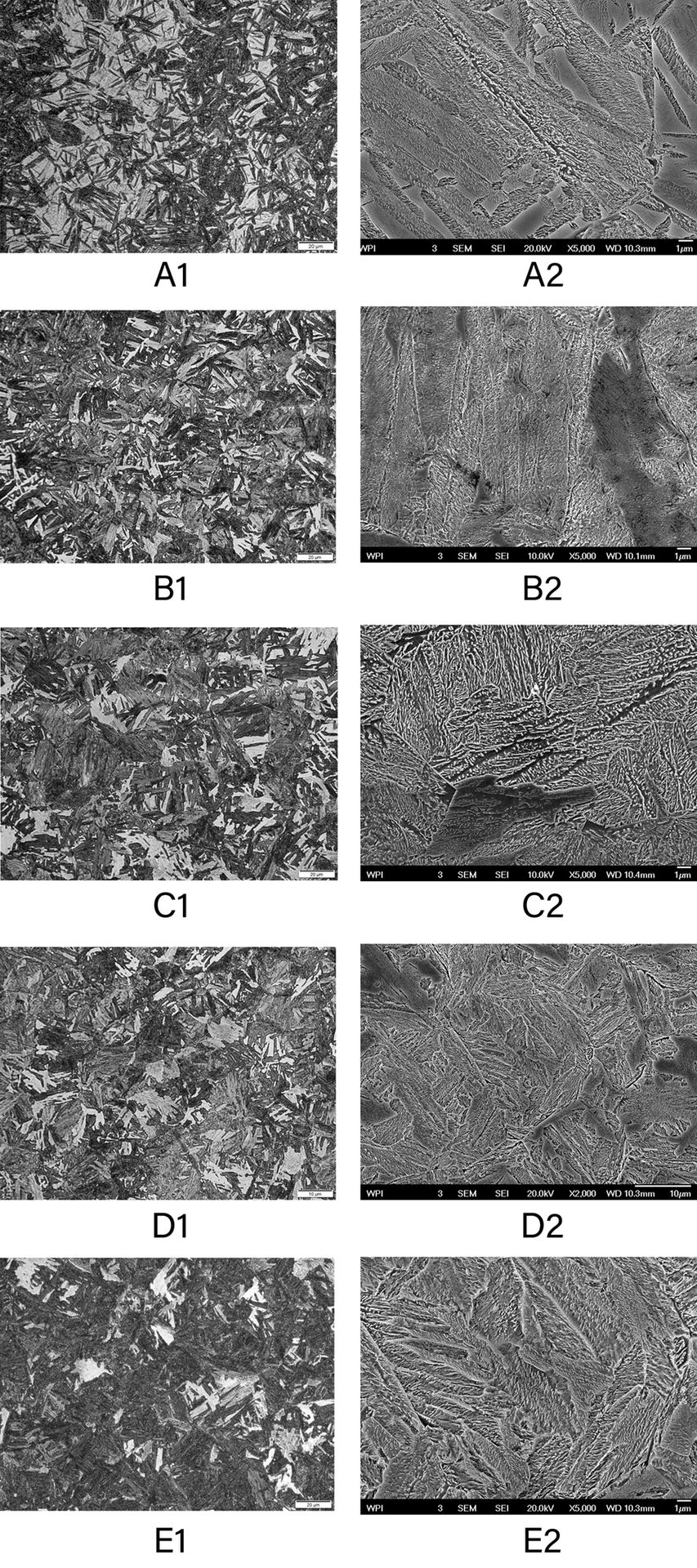
The samples were cut, mounted, polished and etched by 4 vol.% Nital for the microstructure analysis on the sample cross section by optical and scanning electron microscope (SEM). The optical and SEM micrographs are shown in Fig. 6, with optical ones on the left side and SEM ones on the right side. It can be seen that the bainite percentage increases with the austempering holding time increasing. The microstructure of the sample with 30 minutes austempering holding time (Fig. 6d) is similar to the microstructure of the sample with 90 minutes austempering holding time (Fig. 6 e), which shows the formation of the full bainite.
Fig. 6. Optical and SEM micrographs of 1 minute (a), 2 minutes (b), 5 minutes (c), 30 minutes (d) and 90 minutes (e) austempered samples from the third fluidized-bed trial on cross section. The optical micrograph is on the left, and the SEM micrograph is on the right.
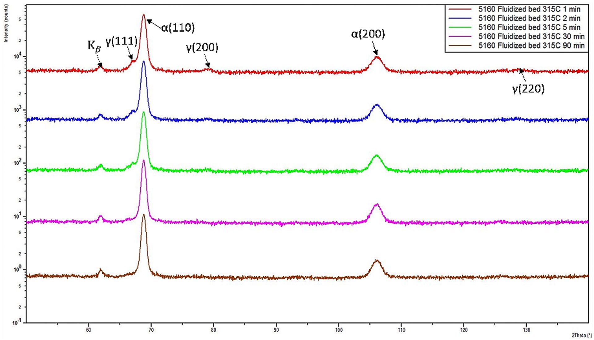
The XRD analysis was also carried out on these as-polished austempered samples. The XRD patterns are shown in Fig. 7. Both bcc (α) and fcc (γ) are identified for the austempered samples with 1, 2 and 5 minutes austempering holding time, while only bcc (α) was identified for the sample with 30 and 90 minutes austempering holding time. The fcc is retained austenite, and the bcc is bainitic ferrite plus martensite. Therefore, the XRD analysis shows that the full bainite forms in the samples with 30 and 90 minutes austempering holding time, which is in good agreement with the hardness measurement and microstructure analysis.
Fig. 7. XRD patterns for 1 minute (red), 2 minutes (blue), 5 minutes (green), 30 minutes (purple) and 90 minutes (brown) austempered samples from third trial with G4Q.
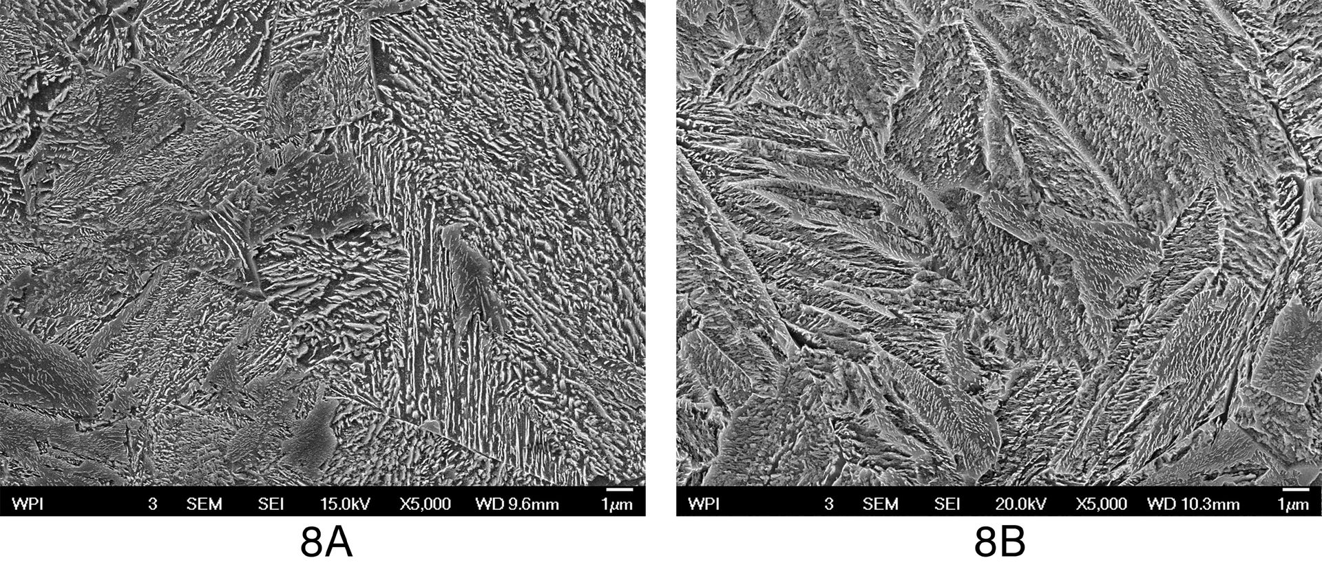
The SEM micrographs of the samples with 90 minutes austempering holding time from the second and third fluidized-bed austempering trials are compared in Fig. 8. With high magnification, the pearlite can be seen in the sample from the second trial (Fig. 8 a), while the full bainite forms in the sample from the third trial (Fig. 8b).
Fig. 8. SEM micrographs of the samples from the second (a) and third (b) trials with 90 minutes austempering holding time.
Conclusion
The trials have shown that with optimized parameters in a fluidized-bed system, which are mainly a special gas and the new bath medium G4Q, almost the same cooling rates can be achieved as in a salt bath. The required cooling effect for 100% austempering of AISI 5160 was fully achieved. This could be proven by metallographic investigations and mechanical material testing.
Fluidized-bed systems from Schwing Technologies now offer an excellent alternative to salt bath for this application. For many other conventional applications, as well as for innovative processes such as the additive manufacturing of metal parts, fluidized-bed systems offer a very good alternative for cooling and quenching. They come with all advantages of salt bath but without its negative environmental impacts, and they can also beat any high-pressure gas-quenching process with respect to temperature uniformity during the actual quenching process. As a result, the treated parts can uniformly transform and keep stresses at a minimum.
For more information: Andreas Guderjahn is a sales engineer and heat-treatment expert at Schwing Technologies GmbH in Germany. He can be reached at a.guderjahn@schwing-tech.com or +49 2845 930 178.
All graphics provided by the author, except where noted.