Proactive Gas Catalytic Oven Maintenance
Extends System Life
Infrared Heating
All images provided by Catalytic Industrial Systems unless otherwise noted
By Shih-Shin Chou,
Catalytic Industrial Systems
The infrared emitter in the gas catalytic ovens has no moving parts and requires minimal servicing to maintain optimal performance.
With proper design and maintenance, gas catalytic ovens can offer years of service with minimal maintenance tasks.
With proper design and maintenance, gas catalytic ovens can offer years of service with minimal maintenance tasks. The major subsystems in an industrial gas catalytic oven consist of the infrared emitter, the fuel gas train, a control panel and an exhaust system. This article will discuss the proper maintenance tasks for these components to help you achieve the most life from your gas catalytic oven.
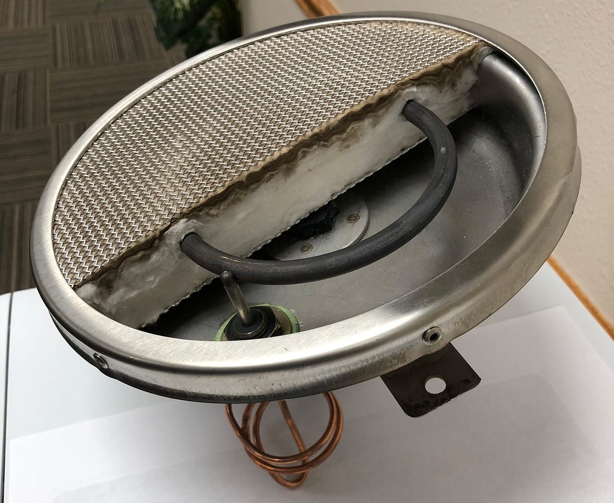
FIGURE 1. While the picture of the example heater shown here is a smaller heater emitter than is normally used in an industrial oven, the internal components are the same as the larger versions.
Infrared Emitter.
The infrared emitter in the gas catalytic ovens has no moving parts and requires minimal servicing to maintain optimal performance. While the example heater shown in figure 1 is a smaller heater emitter than is normally used in an industrial oven, the internal components are the same as the larger versions. The typical operating steps of the gas catalytic heaters are as follows:
- Electric power is first applied to the preheat elements for a total of about 30 min.
- The thermocouple is used to sense that the desired temperature has been reached and, thus, it is safe to introduce fuel gas via the gas train.
- Gas flows into the back of the heater unit and diffuses through the insulation to come in contact with the catalyst pad.
- The gas is converted to infrared heat emitted from the front of the heater.
- Electric power is removed after the preheat cycle.
While the catalysts in the catalyst pad are not consumed during normal operation, taking some simple steps regularly can help to ensure the longevity of the infrared emitters. The emitter surface should be kept clear of any foreign material, including liquid, powder overspray and dirt.
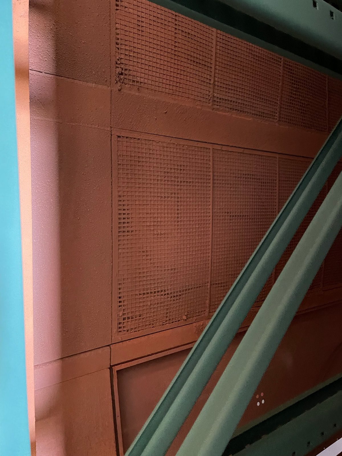
FIGURE 2. This figure shows an infrared emitter panel from an oven that was not functioning. The infrared emitters are coated by the excess powder, rendering the emitters useless.
Figure 2 shows an infrared emitter panel from an oven that was not functioning. This oven had failed after years of neglect. The infrared emitters are coated by the excess powder, rendering the emitters useless. The entire set of infrared emitters needed to be replaced. While the best practice would be to extend the distance between the oven and the powder coat step, this may not be possible in all cases. A simple maintenance step would be to turn the oven at full power to burn off the excess material regularly. For powder-coating applications, a monthly burn-off cycle is recommended. For liquid-coating applications, the burn-off cycle can be applied semi-annually. Finally, a light dusting brush may be used to help knock off any remaining surface material. Never use compressed air or harsh brushes, both of which could damage the heater emitters.
The infrared emitters often can be repaired by the manufacturer to like-new condition. This usually requires the emitters to be removed from the oven so key components can be replaced. Having spare emitters will allow the repair work to be performed without extended downtime.
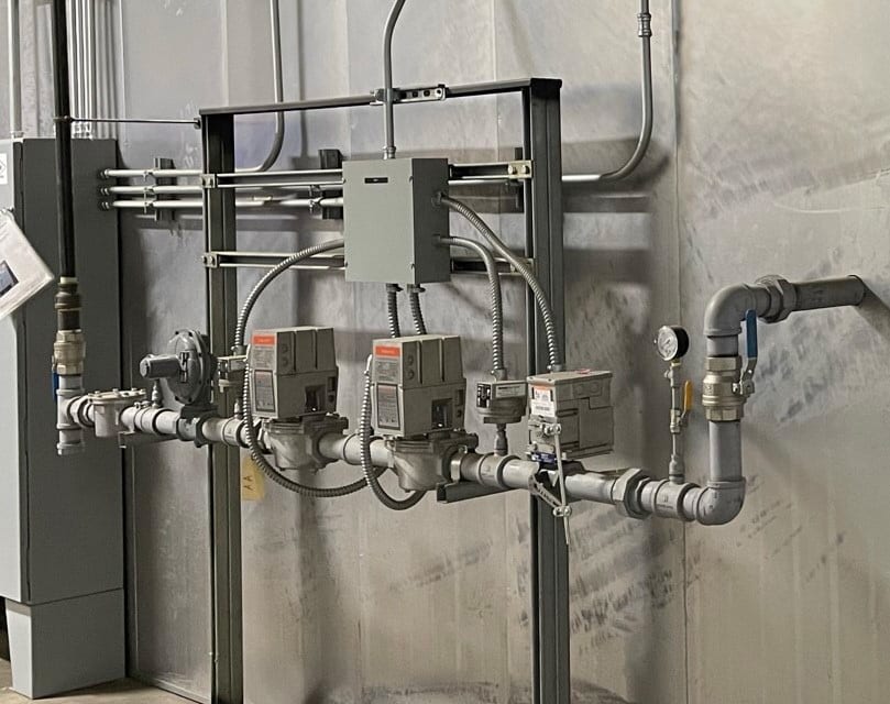
FIGURE 3. Infrared emitters can be arranged as individual units for smaller ovens or in groups called zones for larger ovens. Regardless of the configuration of the infrared emitters, the fuel gas supply is controlled by the fuel gas train.
Gas Train. The infrared emitters can be arranged as individual units for smaller ovens or in groups called zones for larger ovens. Regardless of the configuration of the infrared emitters, the fuel gas supply is controlled by the fuel gas train. The fuel gas train is required by code to have certain components. An example fuel gas train is shown in figure 3.
The filter near the inlet of the gas train is the main item that needs regular servicing. The frequency of the service depends on the quality of the fuel gas. The rest of the components shown in the example gas train do not require regular service; however, having spare parts can be helpful to minimize downtime should replacements be required.
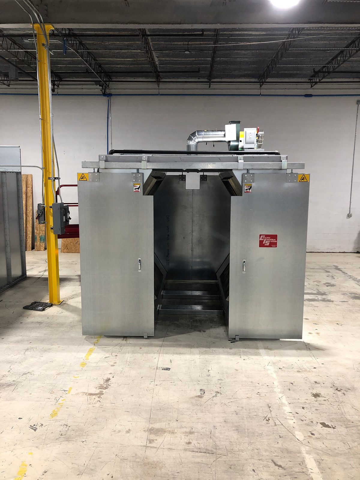
FIGURE 4. An exhaust system will be installed in all ovens, while a recirculation system will only be used in some cases.
Recirculation and Exhaust Systems. An exhaust system will be installed in all ovens, while a recirculation system will only be used in some cases (figure 4). Both systems will have a fan that will require periodic servicing. The motor bearing in the fans should be lubricated as suggested by the manufacturer.
Control Panel and Enclosure. The enclosure of the oven will require the least amount of maintenance if any. Service is usually only required due to external damage. Under normal operating conditions, the enclosure should last the life of the oven.
In most instances, the infrared oven will be controlled with a PLC-based control panel. A qualified electrician may be needed to replace switching components, such as relays, when their working limits have been reached. Most control panels function with minimal servicing or maintenance.
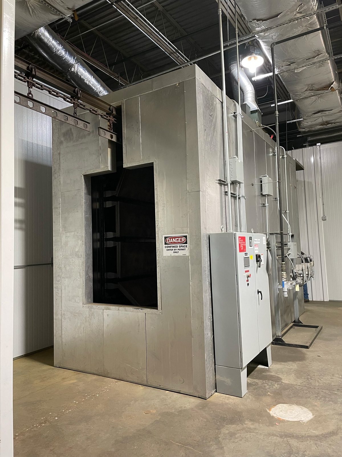
FIGURE 5. In most instances, the infrared oven will be controlled with a PLC-based control panel. Most control panels function with minimal servicing or maintenance.
In conclusion, with proper care and regular cleaning, a gas catalytic infrared oven can provide years of worry-free operation. As in all cases, proper design and installation of the system will be a critical factor in extending the life of the oven. The system should be designed to prevent the overspray of paint from reaching the inlet of the oven. This will help to keep the infrared emitters operating at optimal levels while minimizing the maintenance required. In most instances, natural gas from the gas companies will be clean and dry, but that is not always the case. Regularly cleaning out the fuel gas filter in the gas train will help extend the life of the infrared emitters.
It is good practice to have some spare parts as recommended by the oven manufacturer. This will help to keep downtime to a minimum should maintenance be required. Spares such as extra infrared emitters, thermocouples, gas train components and relays used in the control panel are good items to have on hand for quick change out.
Shih-Shin Chou is the vice president of sales and marketing with Catalytic Industrial Systems. The Independence, Kan.-based company can be reached at 620-577-4711 or visit www.cat-group.com.