How to Use an Offset
for Tuning a Temperature Measurement Control Loop
Temperature Control
Photo: chinaface / E+ via Getty Images
By Bill Bergquist,
Burns Engineering Inc.
An offset used to correct for steady-state errors can prove to be a good tool.
Temperature is one of the most measured variables in process control and plays an important part in ensuring product quality and process efficiency. A common — and accurate — device for measuring temperature is the platinum resistance thermometer (PRT), commonly referred to as a resistance temperature detector (RTD) or a Pt100.
When connected to the process control loop, this temperature-sensing device can provide accurate, stable and repeatable data to the process controller. That is, until something goes wrong. Then what happens? Do you enter an offset or bias in one of the devices in the control loop? Do you shut down and calibrate each instrument separately? Or, perhaps it is due to an installation error with the RTD? This article will provide some guidance.
Using an Offset to Account for Measurement Error
When is using an offset to correct a temperature measurement error an acceptable method? Before we can answer that, we need to look at temperature measurement error sources.
Error sources can be categorized as instrument errors and installation errors. Instrumentation errors are those that are inherent in the instrument design. Typically, they are very small and easily verified by calibrating the device. The main platinum resistance thermometer errors are manufacturing interchangeability, stability and repeatability, and the largest of these is interchangeability. PRT manufacturers adjust the sensor resistance to 100 ohms at 32°F (0°C) to within the tolerances defined by two standards, IEC 60751 or ASTM E1137.

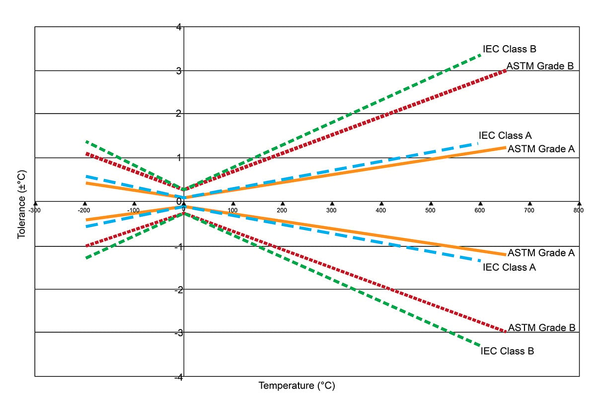
FIGURE 1. This graph shows the tolerance bands labeled as Class or Grade A or B for each standard. The A tolerance at 32°F is ±0.27°F (±0.15°C) and the B tolerance is ±0.468°F (±0.26°C). As the temperature goes higher or lower than 32°F (0°C), the tolerance band gets larger.
All images provided by Burns Engineering Inc. unless otherwise noted
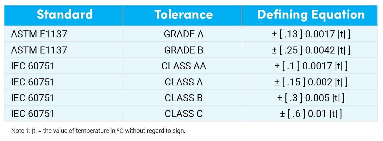
Figure 1 shows the tolerance bands labeled as Class or Grade A or B for each standard. At 32°F, the A tolerance is ±0.27°F and the B tolerance is ±0.468°F. (In Celsius, at 0°C, the A tolerance is ±0.15°C and the B tolerance is ±0.26°C.) As the temperature goes higher or lower than 32°F, the tolerance band gets larger. For example, you may find it surprising that at just 302°F (150°C) the tolerance is nearly ±1.8°F (±1°C) for a Class B RTD. Figure 2 shows equations for calculating the tolerance at any temperature in Celsius and includes Classes AA and C.

FIGURE 2. This chart includes equations for calculating the tolerance at any temperature in Celsius and includes Classes AA and C.
These tolerance bands are important to know when testing an RTD because they can be used to determine if the RTD is still in serviceable condition. A resistance test at 32°F that falls within the original sensor tolerance band when new is a good indication that the probe is functioning correctly.
Sensor errors of repeatability, stability and interchangeability should never be corrected with an offset. Using an offset to correct sensor errors without knowing if the sensor is good can mask a serious problem with the platinum resistance thermometer — with the result being an out-of-control process that can damage the product or be a safety concern.
Installation errors that are caused by environmental factors surrounding the sensor can be large and difficult to characterize. The two most common sources are thermal radiation and conduction.
An example of thermal radiation is a platinum resistance thermometer installed near an oven or other heated or cooled process. The external portions of the temperature assembly are heated or cooled by the ambient conditions created by the adjacent process. These temperature changes are conducted to the sensor, causing a measurement error.
Using enough immersion depth in the process, or adequately shielding the sensor assembly, can minimize this error. If that is not possible, this situation can be a good location to use an offset, assuming the offending heating or cooling source is fairly constant.

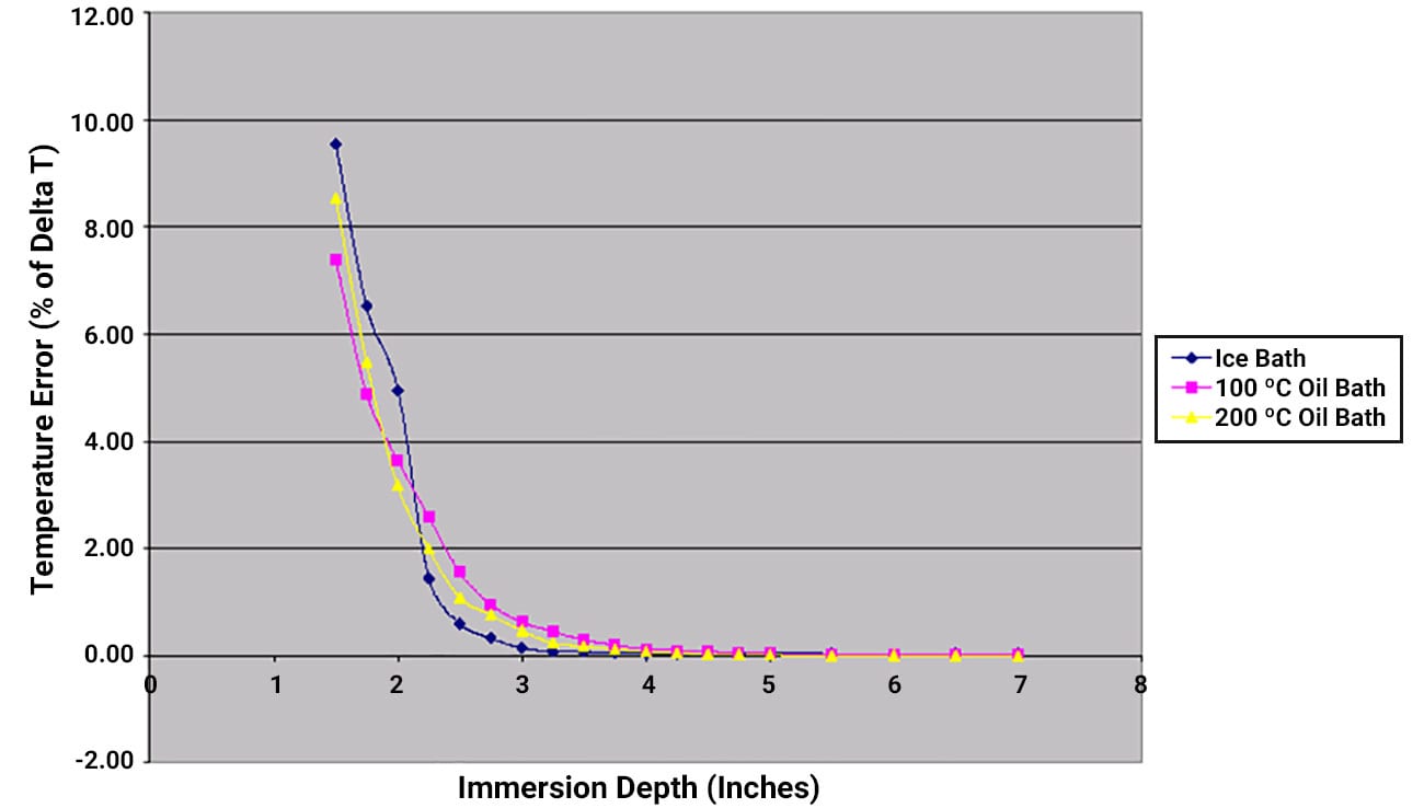
FIGURE 3. The effect of immersion on measurement accuracy for a platinum resistance thermometer installed in a thermowell and exposed to varying depths and temperatures can be seen in this graph.
Conduction errors are the most common source of errors and are usually caused by insufficient sensor immersion in the process. Figure 3 shows the effect of immersion on measurement accuracy for a PRT installed in a thermowell and exposed to varying depths and temperatures.
For this assembly style, the best accuracy is obtained at around 4" immersion. At less than that, the error increases dramatically. If this error cannot be eliminated by correcting the installation with more immersion or insulating the external portions of the sensor, then an offset can be a good solution. The amount of offset can be approximated by placing temporary insulation around the external portions of the sensor and noting any change in temperature.
One caution though: Be aware of any variables that may affect the ambient conditions surrounding the sensor. A customer called recently with a measurement problem in a newly validated system. After entering full production, the sensor was not reading correctly. We eventually identified the source as a fan that had been set up shortly after validation to cool an operator nearby. It also cooled the sensor!
How to Test for and Apply an Offset
A procedure for determining when a PRT is working correctly and when an offset is acceptable was shared by a customer. I think the most important point is the second sentence: “The offset is never to be used to correct a faulty or drifting RTD.” Great advice!
The following is their procedure. (Note: The RTD adjustment is called a bias in some devices and an offset in others.)
Before beginning the offset procedure, keep the following in mind: The offset is never to be used to correct a faulty or drifting RTD. Also, note that a ±2°F (±1.1°C) limit on the total offset is used. The RTD can drift within the tolerance listed in Step 4 in the same direction for several calibrations. This drifting means the RTD has become unreliable and may have lost its repeatability. In such cases, it must be replaced.
- Verify temperature under flowing conditions, if possible.
- In no- or low flow situations, verify temperature in a fluid bath medium.
- Record “as found” temperatures.
- If the temperature indicated does not match the test instrument within verification tolerance requirements and the error is less than ±0.5°F (±1.39°C), correct to the actual verified temperature. If the error is greater than ±0.5°F, perform the following:
Remove the RTD or thermocouple and insert it and your test standard into a liquid bath and verify the temperature.
If the test standard and measured temperature agree within ±0.5°F, there is most likely a heat transference issue between the recording and the test thermowells. Confirm both wells are inserted sufficiently into the flowing fluid stream and that there is sufficient flow.
Correct any issues and re-verify temperature under flowing conditions.
a)
b)
c)
If the difference still exists after performing items under Step 4, verify all wiring connections to ensure that there is no corrosion or loose connections present.
If the verified test temperature and measured temperature differences greater than ±0.5°F continue to exist after completion of all items under Steps 4 and 5, replace the RTD.
If an RTD calibration requires an offset adjustment, the temperature also must be verified at a second point at least 10°F (5.6°C) from the first verification point to confirm that there is no span-related calibration error.
If the total offset is greater than ±2°F (±1.1°C), the RTD has drifted and must be replaced.
Record the “as left” temperatures.
5.
6.
7.
8.
9.
In conclusion, an offset used to correct for steady-state errors such as conduction and thermal radiation can be a good tool to use. I would caution against using an offset to correct sensor errors. Doing so can mask a serious problem with the platinum resistance thermometer and lead to an out-of-control process that can damage the product or be a safety concern.
Body
Bill Bergquist is the principal applications engineer at Burns Engineering Inc., Minnetonka, Minn. For more information from Burns Engineering, call 952-935-4400 or visit burnsengineering.com.


