HYDRONICS WORKSHOP
BY JOHN SIEGENTHALER
Methods from Millinocket
One town in Maine is leading the way in hydronics technology and transactive energy management.

Most of you reading this probably don’t know much about Millinocket, Maine. It’s a small community a little over an hour’s drive North of Bangor. The former location of two large paper mills is now without those anchor industries and working to redefine its future. It’s not where you would expect innovative research involving hydronic heating to be taking place. But, you’d be mistaken…
Millinocket is located close to utility scale wind turbine “farms.” The winter winds blow strong in that area: so strong that at times the wind turbines combined with other nearby renewable generating sources such as hydro-electric dams, produce more electrical power than the grid serving that area requires.
It might seem intuitive that when such “over generation” occurs the solution is to shut down some of the generation equipment, but that’s not as simple and quick as turning off a switch. When a wind turbine is not producing power, its economic return on investment is degrading, and its contribution to renewably-generated electricity is zero. A similar scenario applies to hydropower. The solution is not to curtail generation, it’s to find ways of off-loading surplus power to loads that can accept it.
One way to deal with over generation without curtailing renewably-sourced electricity generation is to reduce the wholesale cost of that electricity and offer it for sale to other utilities. Some utilities use data for load trends and weather forecasts to establish wholesale pricing for electricity 48 hours in advance. Other utilities can then decide what amount of electrical energy (megawatt•hours) they need, and what price they are willing to pay for that power. This “transactive” approach to grid management has been used for years. It’s also proving to be a key concept for optimizing the use of renewably-sourced electricity.
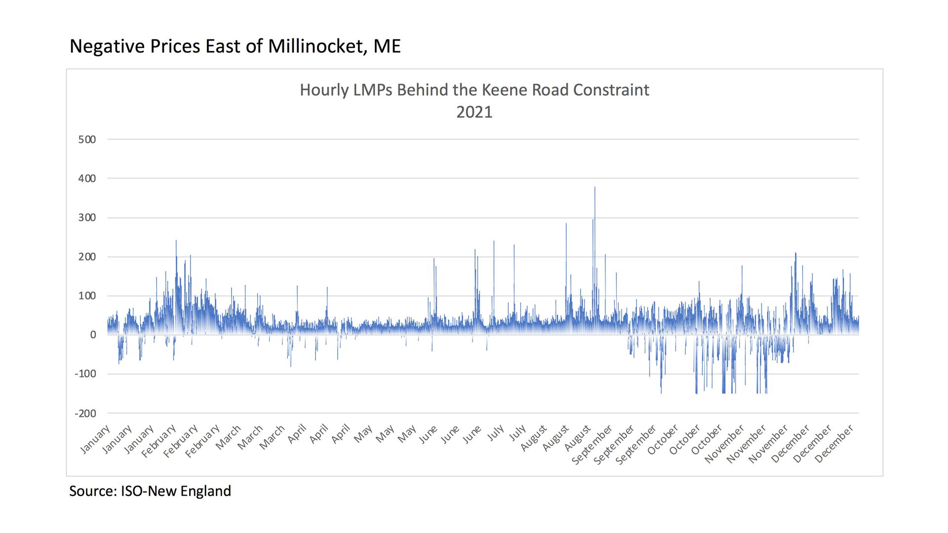
Deal or no deal: To entice other utilities to purchase surplus power the utility wanting to sell it sets its “willing to sell” wholesale price for each of the next 48 hours. In some cases that “price” can be negative. That’s right; at the wholesale level there are times when one utility will pay another utility to accept their surplus power. This has occurred in utility districts with abundant solar and wind power generation, and in some cases the negative pricing can last for several hours.
Figure 1 shows an example of how the wholesale price of electricity (in Megawatt•hour) can vary in the Millinocket area. Any portions of the graph below 0 represent negative prices. LMP stands for locational marginal pricing.
ENLARGE
FIGURE 1
Courtesy of GridWorks Consulting
To sell electricity, there has to be a willing buyer and a way to move that power. The latter is a major constraint in the Millinocket area. The physical limits of the local power grid cannot always accommodate the need to wheel all surplus power.
Too much of a good thing: Imagine what you could do with an air-to-water heat pump capable of producing water at temperatures of 170ºF or more, thermal storage and a retail utility rate that sets the price of electricity, on an hourly basis, 48 hours into the future. During some of those hours, electricity might cost upwards of $0.40 / kwhr. At other times, it might be less than $0.07 / kwhr. And, at still other times, it might be less than $0.00 / kwhr!
I suspect your first thought is to purchase the electricity when its price is lowest, convert it into heat using the heat pump, and store that heat in insulated tanks of water. Well - you’re on the right track, but it gets a bit more complicated.
First, there must be assurance that the building being heated by this approach has consistent comfort - regardless of fluctuations in electricity prices. Another consideration is available: thermal storage capacity and the associated temperatures (i.e., you can’t store heat at 180 ºF if the heat pump can only produce 170 ºF). Another is the limitation of the heat emitters (i.e., you can’t drain storage down to 100 ºF, if the heat emitters can’t sustain building comfort using those relatively low water temperatures). Although the overall concept of such a system makes sense, the details of how to control it, in an optimal way, can be complex.
Back in Millinocket: A company named GridWorks Consulting, working with a partner company - Ridgeline Analytics, a local heating professional Paul Moscone, and with support from Efficiency Maine, is conducting research on how to create hydronic heating systems that reduce dependency on fuel oil by leveraging the advantages of “transactive” management of electricity.
That research is not all theoretical. It involves multiple installations in existing “average” homes in Millinocket. Those systems have extensive control and monitoring hardware. They were built to demonstrate what’s possible, and the results to date have been both impressive and encouraging.
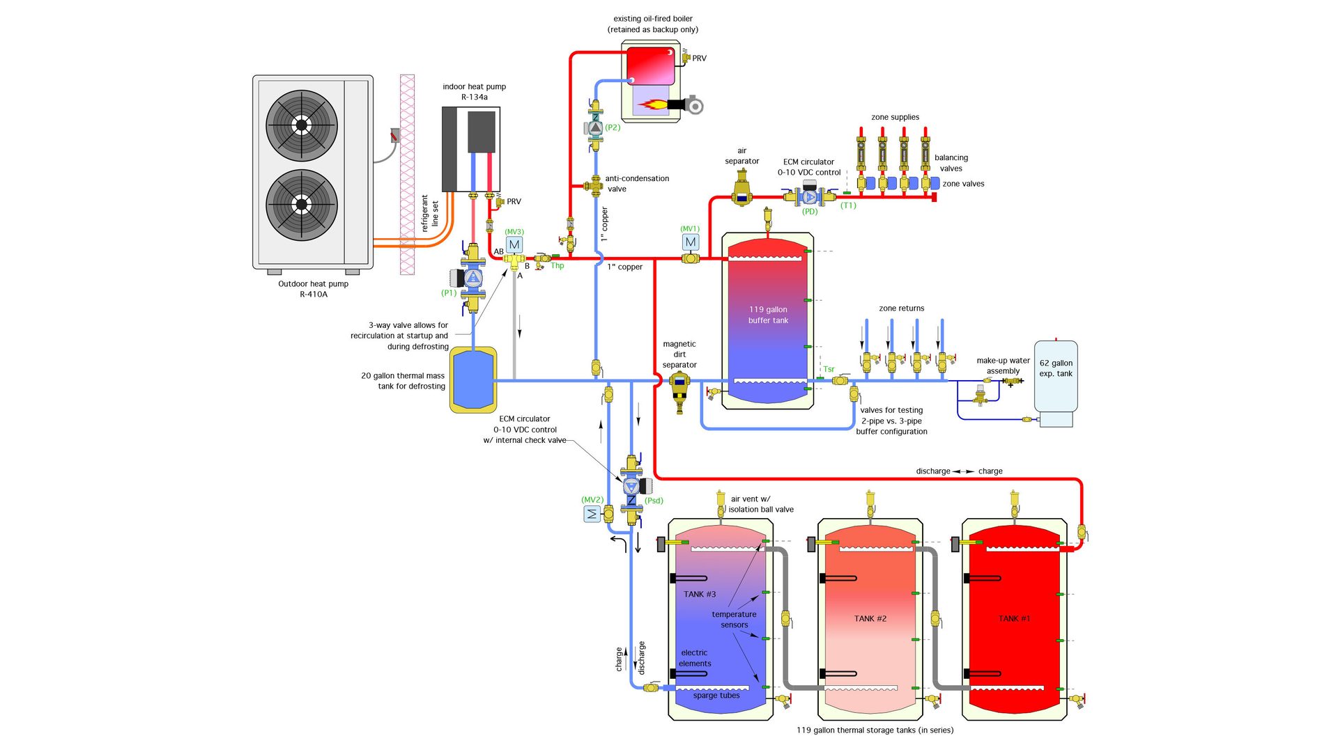
Figure 2 shows the piping concept for one of the installations.
ENLARGE
FIGURE 2
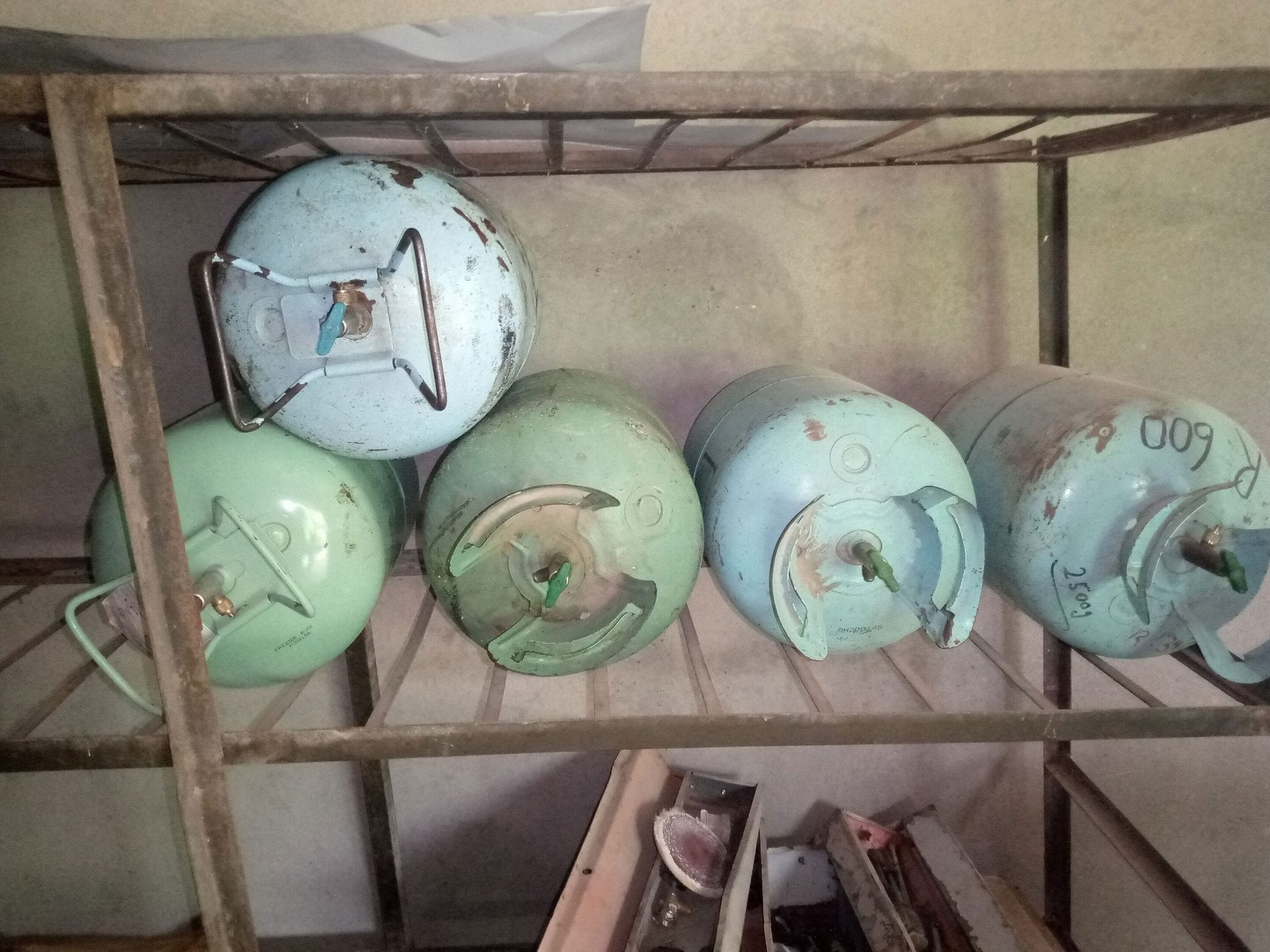
The systems in Millinocket use high temperature “cascade” air-to-water heat pumps capable of producing 180 ºF leaving water temperature. Those cascade units have an outdoor heat pump running on R-410A refrigerant that routes refrigerant from its condenser to the evaporator of an indoor heat pump running on R-134A refrigerant. The outdoor unit “lifts” the temperature of the refrigerant from below that of outdoor air to an intermediate level. The indoor heat pump “amplifies” that temperature higher than what a current generation air-to-water heat pump running a single refrigerant cycle can create: high enough to transfer heat to water at 180 ºF.
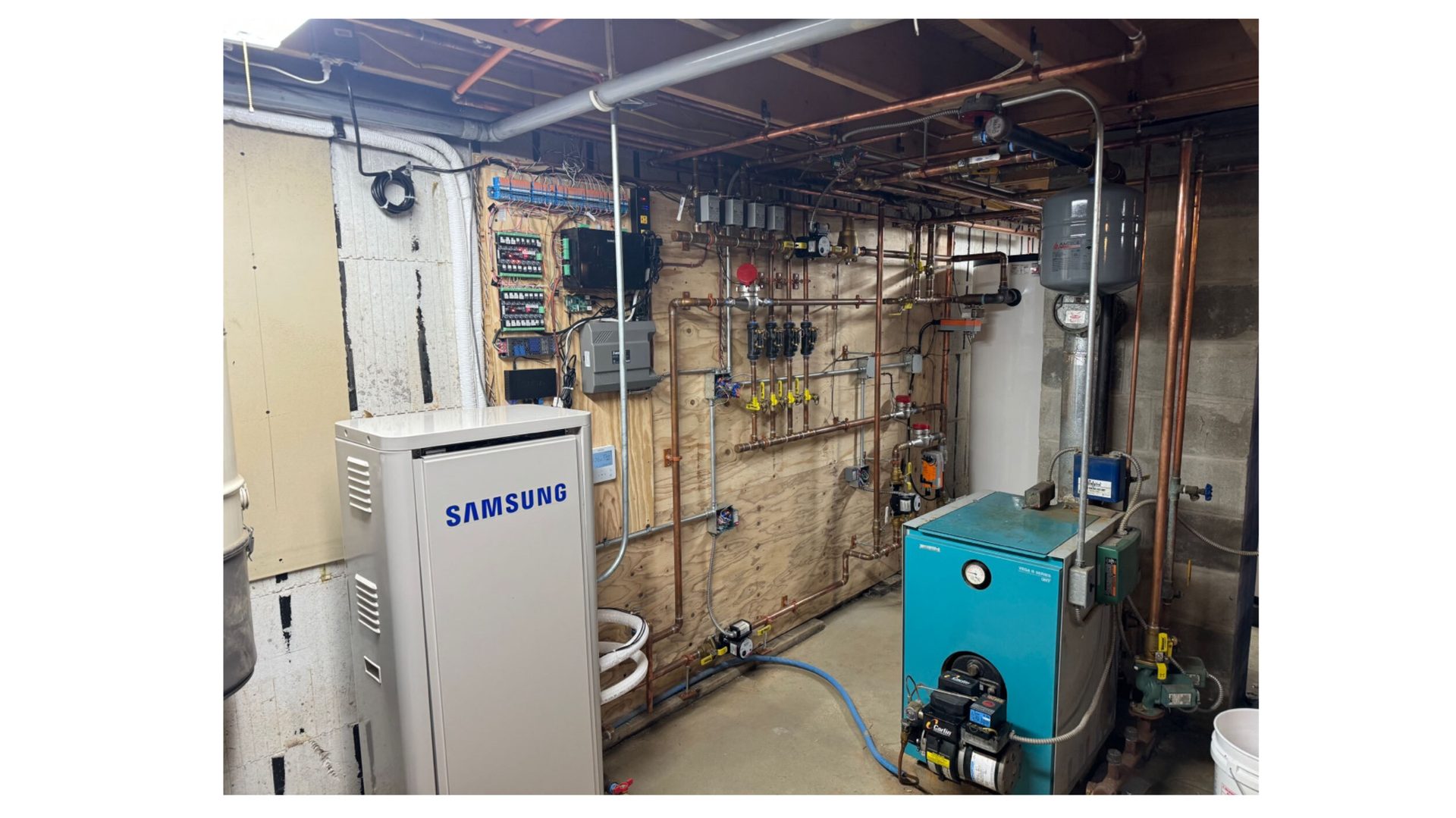
One of these cascade heat pumps was retrofitted to a system that had an oil-fired boiler serving 4-zones of fin-tube baseboard. The existing boiler, seen in figure 3, was retained as a backup heat source.
ENLARGE
FIGURE 3
Courtesy of GridWorks Consulting
The initial configuration of the system includes a 119-gallon buffer tank, along with three 119-gallon electric water heaters used as thermal storage tanks and piped in series. Figure 4 shows these tanks.
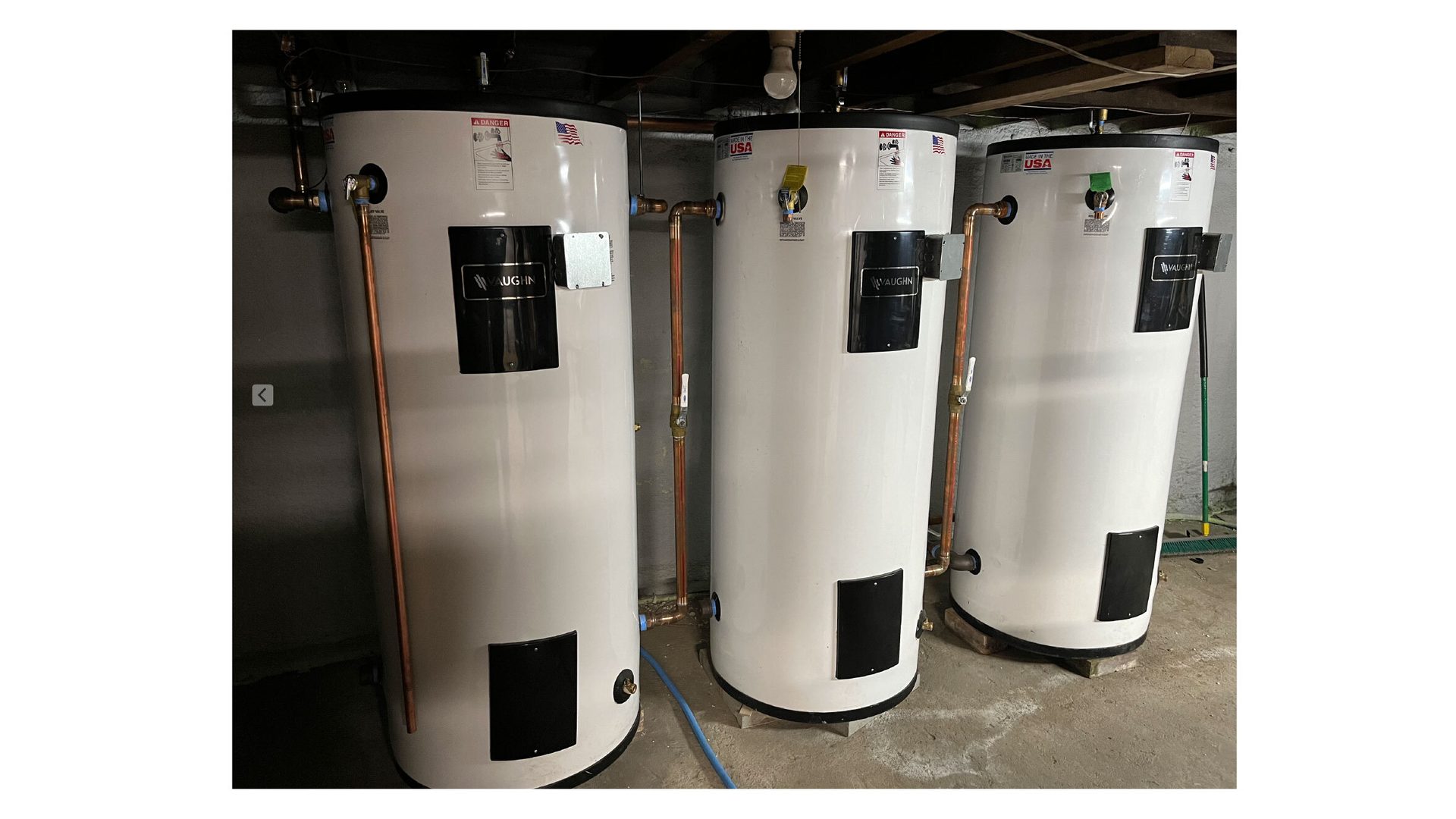
ENLARGE
FIGURE 4
This series piping configuration allows good temperature stratification. The coolest water is in the lower portion of the right tank, while the hottest water is in the upper portion of the left tank. All three tanks include “sparge tube” diffusers to minimize mixing currents that would otherwise disrupt temperature stratification.
The electric elements in these tanks are currently not used, but could be configured to capture low-cost electrical energy beyond that used by the heat pump. If used this way, they can respond instantly, which is important since some transactive electrical offerings might only last a few seconds.
Look back at figure 2. To put heat into storage the heat pump operates along with its circulator (P1). Motorized valve (MV1) is closed, forcing flow into the upper portion of thermal storage tank #1. Water from the lower portion of tank #3 flows back to the heat pump through motorized valve (MV2). During this time the buffer tank can provide some heat delivery to the distribution system. However, if the buffer tank runs low on heat valve MV1 opens to allow the buffer to be heated from the heat pump. This ensures that comfort is not compromised in the process of charging thermal storage.
To remove heat from thermal storage, circulator (P2) operates at variable speed, which is controlled by a 0-10 VDC signal from the system’s controller. The flow of hot water passes through valve (MV1). The heated water from thermal storage can blend with water from the upper portion of the buffer tank as required to maintain a target supply water temperature to the heat emitters. That target temperature is based on outdoor reset.
Tiny tank: One “nuance” of many air-to-water heat pumps is that they turn on their circulator 2-3 minutes prior to starting their compressor. During this time, the heat pump’s internal controller measures flow rate and verify that adequate and stable flow is present prior to starting the compressor(s). Although this action is prudent in protecting the heat pump against inadequate flow, it can destroy beneficial temperature stratification in the thermal storage subsystem by circulating water from the lower portion of the coolest tank to the upper portion of the hottest tank.
One work around is to “recirculate” flow exiting the heat pump back into the heat pump until the leaving water temperature is slightly higher than the temperature at the top of the “hot” thermal storage tank. From a piping standpoint, this is easily done using a 3-way diverter valve.
To sell electricity, there has to be a willing buyer and a way to move that power. The latter is a major constraint in the Millinocket area. The physical limits of the local power grid cannot always accommodate the need to wheel all surplus power.
Another situation that can disrupt temperature stratification in storage is when the heat pump goes into defrost. During this time, the heat pump operates in cooling mode, pulling heat from “something” inside the building, and using it to melt frost on the outdoor coil. For the system in figure 1, that “something” is a small tank piped so that it’s part of the recirculation circuit through motorized valve (MV3). A 20-gallon tank can supply defrost heat for a nominal 4-ton heat pump for about 8 minutes, which is typically adequate to complete a defrost cycle. Other defrosting control scenarios are possible, including temporarily operating all the zones to scavenge heat from the building, or tapping into the thermal mass in the lower portion of the coolest thermal storage tank.
The brains: Over the last several decades, the controls used in hydronic heating systems have ranged from crude bimetal switches to capillary tube aquastats, to little glass tubes containing a few drops of mercury, and finally to microprocessors. The systems being tested in Millinocket take it a step farther. They use a Raspberry Pi microcomputer as both a local controller and a means of accessing online energy cost and weather forecasting data. That little computer costs about $40. It accepts inputs from several temperature sensors and flow meters and uses that information along with some very specific programing to coordinate the operation of every valve, circulator, or other controllable device in the system. It’s also used to log and report system performance information.
The Raspberry Pi can’t directly power 24VAC or line voltage devices, but that’s easily handled by using the digital outputs from the Raspberry Pi to drive relays that switch line voltage devices on and off.
Figure 5 shows the Raspberry Pi™ microcomputer and one of the relay boards it drives.
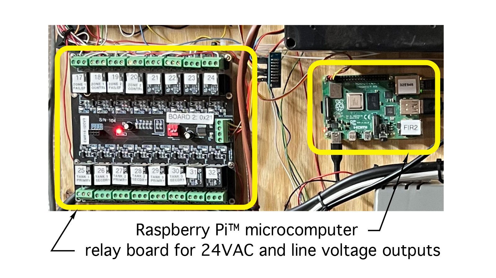
ENLARGE
FIGURE 5
You may be thinking, what happens to this system if the internet connection is lost? The people at Gridworks definitely planned for that contingency. If the internet connection is lost the system automatically goes into a safe “local control” mode. If the Raspberry Pi computer fails, the system automatically reverts to its original oil-fired boiler mode.
Why this is relevant: Research systems are built to test concepts and find potential “weak points” in those concepts. The process comes down to test, observe, refine, and repeat.
The systems just described are works in progress. Still, from what I’ve seen so far, their operation is impressive. One system was able to maintain stable comfort in the home through nights with -5 ºF outside temperatures while running the heat pump only during off-peak (low cost) electrical periods.
Figure 6 shows minimal variation in the hot water temperature supplied to the zone circuits while the heat pump was operating as well as during on-peak electrical periods up to 5 hours long, when the heat pump was off.
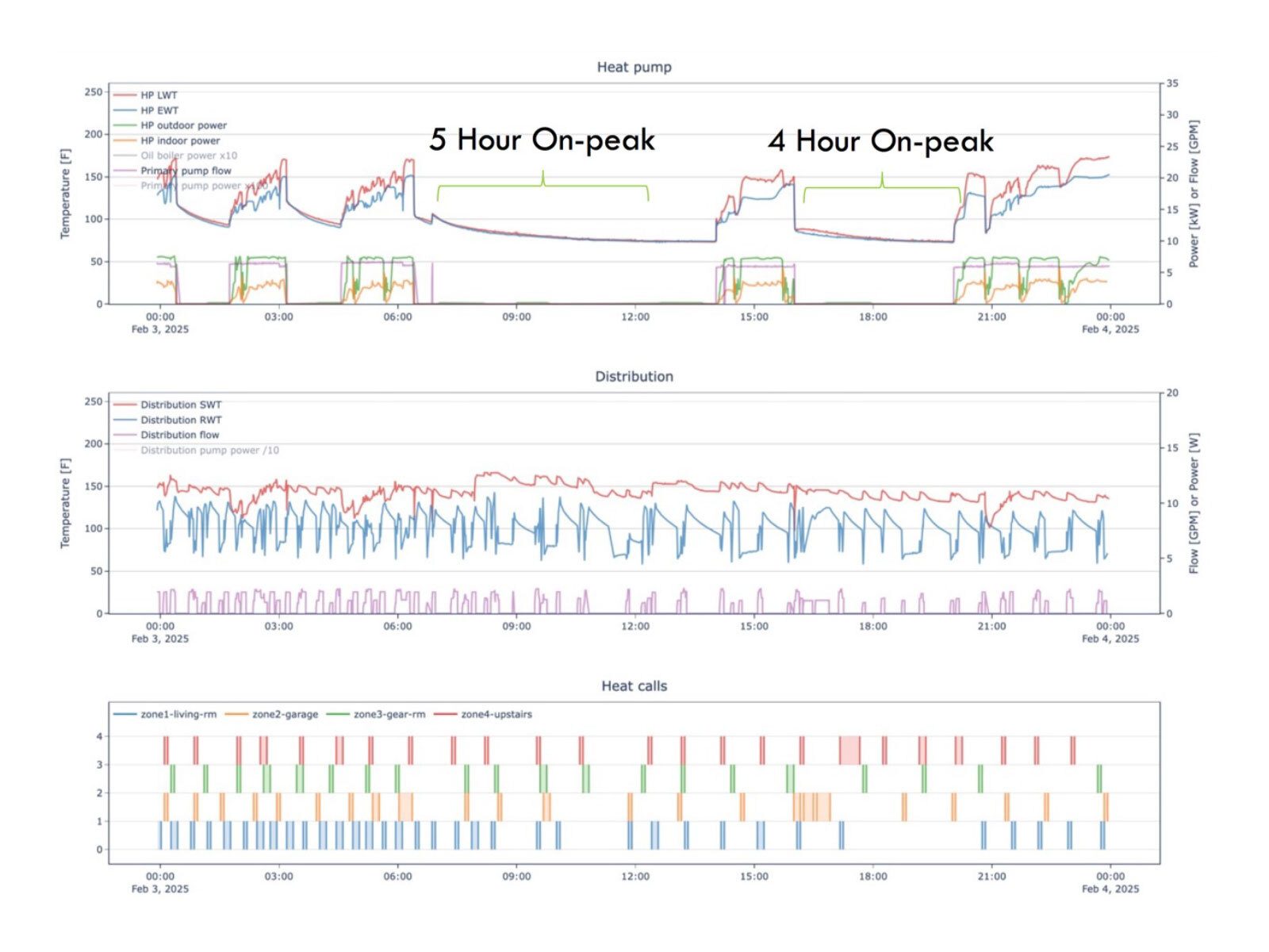
ENLARGE
FIGURE 6
Courtesy of GridWorks Consulting
I’ve been fortunate enough to work with the team that designed, installed, and operated these research systems. In my opinion, they are exploring concepts that are far beyond what the current North American hydronics industry deals with on a day-to-day basis. Continued work on these systems will lead to refinements in both the hardware and software used for transactive energy management. Test results from these systems may eventually lead regulators to approve different electric rate structures that could benefit both the customer and the utility. Those results could also be laying the groundwork for how hydronics technology is applied in the future.
The unassuming town of Millinocket, Maine might someday be known as the place where hydronics technology first teamed up with transactive energy management.

Lead image courtesy of DenisTangneyJr / iStock / Getty Images Plus
John Siegenthaler, P.E., is a consulting engineer and principal of Appropriate Designs in Holland Patent, New York. In partnership with HeatSpring, he has developed several online courses that provide in-depth, design-level training in modern hydronics systems, air-to-water heat pumps and biomass boiler systems. Additional information and resources for hydronic system design are available on Siegenthaler’s website, www.hydronicpros.com. Contact him at hydronicprosjm@gmail.com.